
Main cotton carding roller shaft bearing seat airflow protective device of carding machine

A technology of protection device and bearing seat, which is applied in deburring device, fiber treatment, textile and paper making, etc. It can solve the problems of simple carding machine, extreme viewing effect, increased energy consumption, and lack of simplicity, so as to ensure the viewing effect , reduce the burden of inspection, the effect of simple structure

Active Publication Date: 2015-03-25
常熟市伟成非织造成套设备有限公司
View PDF10 Cites 17 Cited by
  • Summary
  • Abstract
  • Description
  • Claims
  • Application Information

AI Technical Summary

Problems solved by technology

But, there is following technical problem in this patent scheme: one, owing to needing to arrange air collecting pipe on the main carding roller shield and connect one end of connecting pipe on the suction nozzle of air collecting pipe, connect the other end of connecting pipe to the corresponding The side cover of the main carding roller at both ends of the main carding roller, thus causing the structure of the carding machine to be bloated and unsophisticated; secondly, due to the need to equip the air collecting pipe with a negative pressure generating device, the cost increases, and due to the negative pressure The pressure generating device is supported by electric energy, thereby increasing energy consumption; third, because the function of the edge suction device is to absorb the fibers entering between the end of the main carding roller and the bearing seat of the roller shaft, it is passive rather than positive. Because the fibers escape from the end of the main carding roller will affect the thickness uniformity of the cotton web laid out by the web-laying machine in the subsequent channel, the thickness of the cotton web will appear thick in the middle and thin on both sides, making the final The weight of non-woven products processed by needle punching machine or spunlace machine is inconsistent, which seriously affects the quality of non-woven products; Fourth, if the fibers sucked by the edge suction device cannot be used, it will cause waste of raw materials
[0005] The invention patent authorization announcement number CN101509158B provides the "edge blowing device for carding machine" (the patent was proposed by the applicant) to a certain extent, which can make up for some of the shortcomings of the aforementioned CN101250774B. For details, please refer to the specifications of this CN101509158B Nos. 0003 to 0004 and 0007 and 0013 paragraphs, but there are still the following shortcomings: First, because the main air pipe, inlet and outlet air passages and air passages need to be constructed, the processing is more cumbersome; The air pipe is exposed to the outside, so it is still not enough to make the carding machine concise and visually effective, and once the air supply pipe is damaged and not found or replaced in time, the fiber will still enter the roller bearing seat and appear on the roller bearing. The third is that it is necessary to configure an air source device such as a blower for the main air pipe (see paragraph 0020 of the manual), which is not conducive to saving electric energy, and it will also increase the size of the carding machine due to the equipment of these auxiliary devices. The cost of the whole machine

Method used


Image

  • Main cotton carding roller shaft bearing seat airflow protective device of carding machine
  • Main cotton carding roller shaft bearing seat airflow protective device of carding machine

Examples


Embodiment Construction

[0021] In order to enable the examiners of the patent office, especially the public, to understand the technical essence and beneficial effects of the present invention more clearly, the applicant will describe in detail the following in the form of examples, but none of the descriptions to the examples is an explanation of the solutions of the present invention. Any equivalent transformation made according to the concept of the present invention which is merely formal but not substantive shall be regarded as the scope of the technical solution of the present invention.

[0022]In the following descriptions, all concepts involving up, down, left, right, front and rear directionality (or orientation) are for the position state of the picture being described, and the purpose is to facilitate the public Therefore, it cannot be understood as a special limitation on the technical solution provided by the present invention.

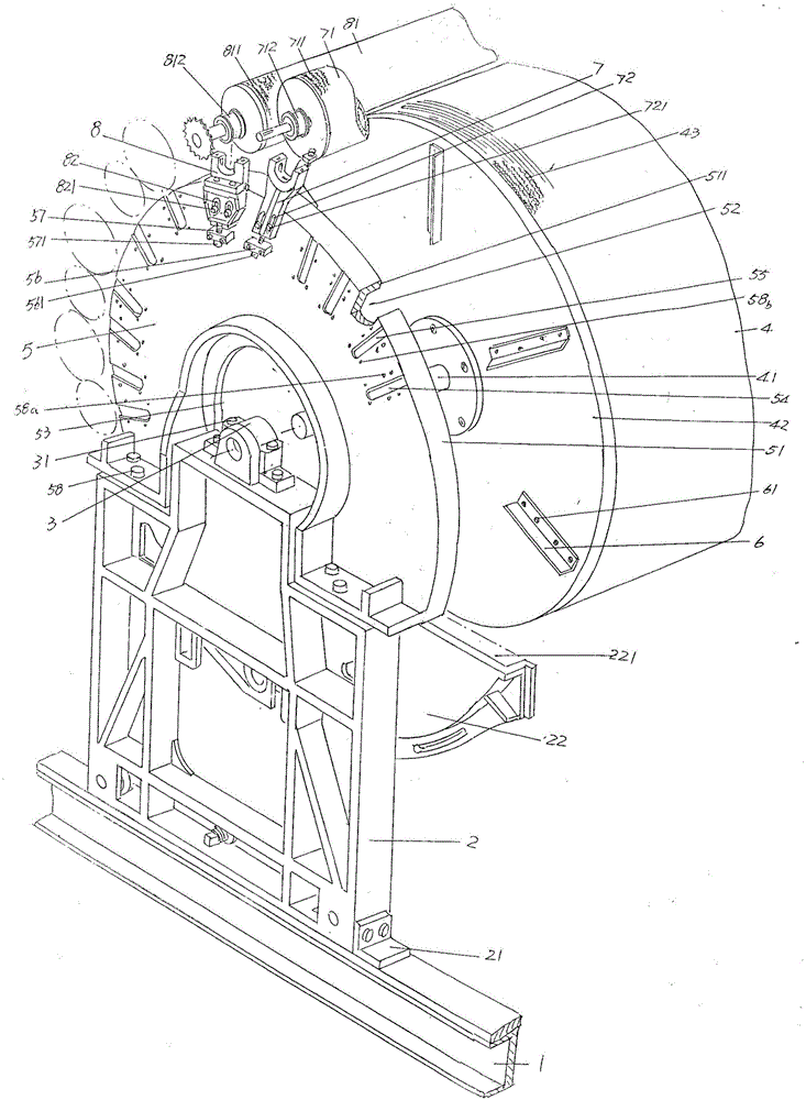
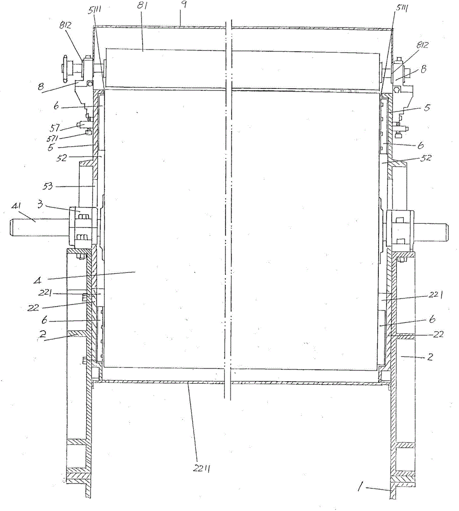
[0023] See figure 1 and figure 2 ,exist figure 1 and ...


PUM


Abstract

The invention provides a main cotton carding roller shaft bearing seat airflow protective device of a carding machine and belongs to the technical field of non-woven fabric machines. The carding machine comprises a base, two main cotton carding roller supporting wall plates fixed to the two sides of the base, roller shaft bearing seats arranged on the tops of the main cotton carding roller supporting wall plates, a main cotton carding roller supported by the roller shaft bearing seats and main cotton carding roller side protective covers fixed to the upper portions of the main cotton carding roller supporting wall plates. The main cotton carding roller shaft bearing seat airflow protective device comprises a groups of blades. The group of blades are distributed in a radial state and fixed to the end face of the side, facing the main cotton carding roller side protective covers, of the main cotton carding roller. The main cotton carding roller shaft bearing seat airflow protective device can prevent fibers from escaping from the ends of the main cotton carding roller to the roller shaft bearing seats, reduce oil consumption, guarantee the overall simplicity and the appearance effect of the carding machine, guarantee that the thicknesses of a web laid by a web laying net on a following-up station are even, and lighten the detection and maintenance load of a manufacturer adopting the carding machine.

Description

technical field [0001] The invention belongs to the technical field of non-woven machinery, and in particular relates to an airflow protection device for a main carding roller shaft bearing seat of a carding machine. Background technique [0002] The aforementioned carding machine is also called a carding machine, which is a part of a complete set of non-woven product production equipment. As known in the industry, a complete set of non-woven products such as non-woven fabrics or non-woven felt production equipment mainly includes an opener, a carding machine, a laminating machine and a needle punching machine (or hydroentanglement machine). The non-woven fibers after opening by the machine are carded and fed to the web-laying machine to lay the web. After the web-laying machine lays the web, it is sent to the needle-punching machine for needle punching or the spunlace machine for spunlace to form a non-woven product. [0003] The main carding roller of carding machine is a...

Claims


Application Information

Patent Timeline
Patent Type & Authority Applications(China)
IPC IPC(8): D01G15/46D01G15/82
CPCD01G15/465D01G15/82
Inventor 王卫成
Owner 常熟市伟成非织造成套设备有限公司
Learn More