Glass fiber yarn constant-tension pay-off device

A glass fiber yarn and pay-off device technology, applied in textiles and papermaking, knitting, warp knitting, etc., can solve the problem that the yarn cutting device does not have the ability to control the tension and keep it constant

Inactive Publication Date: 2015-03-25
SHANGHAI QISHAN INSTR TECH
View PDF1 Cites 1 Cited by
  • Summary
  • Abstract
  • Description
  • Claims
  • Application Information

AI Technical Summary

Problems solved by technology

The yarn cutting device does not have the functi

Method used


Image

  • Glass fiber yarn constant-tension pay-off device

Examples


Embodiment Construction

[0013] In order to make the technical means, creative features, goals and effects achieved by the present invention easy to understand, the present invention will be further described below in conjunction with specific embodiments.

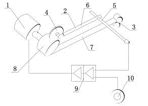
[0014] Such as figure 1 As shown, a glass fiber yarn constant tension pay-off device includes a feed wheel 3, a roller 8 and an electronic control unit 9, the feed wheel 3 and the roller 8 are connected by a tension test belt 7, and the roller 8 and the tension test The sensor 2 is connected between the belts 7, the roller 8 is connected to the brake 1, the sensor 2 is connected to the electronic control unit 9, the electronic control unit 9 is connected to the brake 1, and the electronic control unit 9 is connected to the torque control knob 10; the sensor 2 includes a sensor The wheel 4 is connected to the sensing handle 5, the sensing wheel 4 is connected to the sensing handle 5 through the connecting rod 6, the sensing wheel 4 is connected to ...


PUM


Abstract

The invention discloses a glass fiber yarn constant-tension pay-off device which comprises a feed wheel, a roller and an electronic control unit. The feed wheel is connected with roller through a tension testing belt. A sensor is connected between the roller and the tension testing belt. The roller is connected with a brake. The sensor is connected with the electronic control unit which is connected with the brake and a torque control rotary knob. The glass fiber yarn constant-tension pay-off device is simple in structure and convenient to use; the tension of glass fiber yarn is tested through the tension testing belt, the brake is controlled through the torque control rotary knob according to the pay-off tension of the glass fiber yarn, and the tension is kept unchanged.

Description

technical field [0001] The invention relates to a wire releasing device, in particular to a glass fiber yarn constant tension wire releasing device. Background technique [0002] In the prior art, such as patent ZL201010273760.1 discloses a chopped yarn device for a biaxial warp knitting machine, which includes a frame and an electric cabinet, and the frame is provided with a pay-off mechanism, a chopping mechanism, and a dispersion mechanism; the pay-off mechanism Including the inlet mechanism, several gas pipes and outlet mechanism, the inlet mechanism is provided with a number of gas pipe inlet holes connected with the gas pipe, and the outlet mechanism is equipped with a number of gas pipe outlet holes connected with the gas pipe; the chopping mechanism includes driving rollers and passive rollers arranged in parallel And the pressure roller, the driving roller is set on the frame and driven by a large motor, a number of cutting blades are evenly arranged on the peripher...

Claims


Application Information

Patent Timeline
IPC IPC(8): D04B27/10
CPCD04B27/10
Inventor 倪前东
Owner SHANGHAI QISHAN INSTR TECH
Why Eureka
Try Eureka