Repair technology for drainage pressure reducing well

A technology for draining decompression and decompression wells, which is applied in dams, infrastructure projects, embankments, etc., and can solve problems such as skeleton fracture, strip skeleton aging, and failure to use normally.

Active Publication Date: 2015-03-25
GUANGDONG YUANTIAN ENG
View PDF5 Cites 4 Cited by
  • Summary
  • Abstract
  • Description
  • Claims
  • Application Information

AI Technical Summary

Problems solved by technology

[0003] Existing relief well structures such as figure 1 As shown, the upper section of the well pipe in the relief well is the well pipe 1 of the relief well, and the bottom section is the filter pipe 2, and the filter pipe 2 is provided with a strip-shaped water filter hole 20. The maximum diameter of the relief well with this structure is The problem is that the strip-shaped water filter holes 20 make the filter tube 2 form a strip-shaped skeleton, an

Method used


Image

  • Repair technology for drainage pressure reducing well
  • Repair technology for drainage pressure reducing well
  • Repair technology for drainage pressure reducing well

Examples


Embodiment Construction

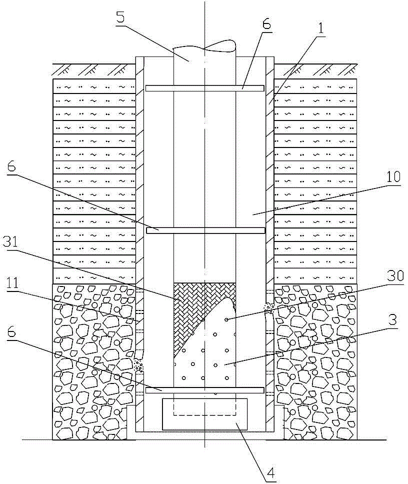
[0023] refer to Figure 2 to Figure 5 , the repairing process of drainage relief well, comprising the following steps.

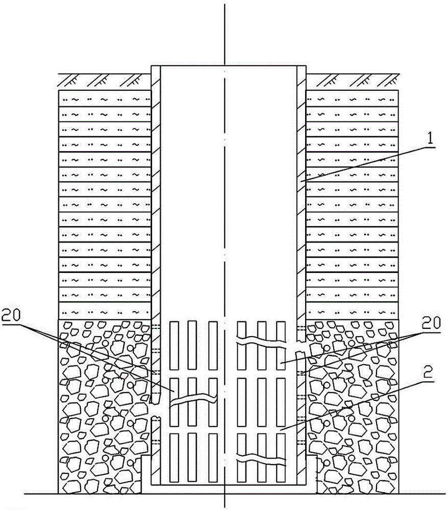
[0024] Step 1), cleaning in the original well: use the cleaning process of the relief well to discharge the sedimentation, sundries and sewage in the well pipe 1 of the original relief well out of the pipe 1 until it is cleaned.

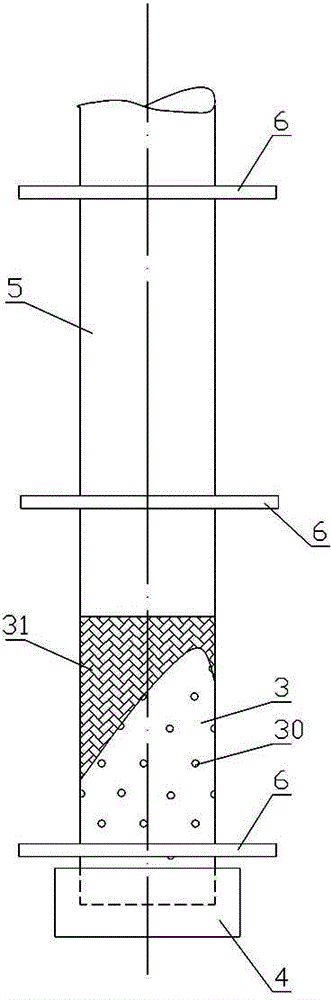
[0025] Step 2), intubation tube preparation: such as figure 2 As shown, the intubation pipe tool includes a pipe plug 4, a filter pipe 3, a filter screen 31, a riser pipe 5 and a steel retainer 6, and the length of the filter pipe 3 is 0.6 mm longer than the original filter pipe 11 of the original relief well pipe 1. The outer wall of the filter tube 3 is evenly distributed with filter holes 30, the outer wall of the filter tube 3 is coated with a filter screen 31, the bottom end of the filter tube 3 is provided with a pipe plug 4, and the top of the filter tube 3 is connected to the top of the water riser 5. The bottom end is c...


PUM

PropertyMeasurementUnit
Particle sizeaaaaaaaaaa

Abstract

The invention provides a repair technology for a drainage pressure reducing well. The repair technology includes the steps that first, cleaning is conducted in an original well; second, inserting tube tools are prepared, the inserting tube tools comprise a filter tube and steel retaining devices, the length of the filter tube is 0.5-1 meter larger than the length of a filter tube of a well tube of the original pressure reducing well, filter holes are evenly distributed in the outer wall of the fiber tube, the outer wall of the filter tube is coated with a filter net, a tube plug is arranged at the bottom end of the filter tube, the top end of the filter tube and the bottom end of a water rising tube are connected to form an inserting tube with the length being larger than the depth of the original pressure reducing well, the steel retaining devices are round pieces with inserting holes formed in the middles, and the diameter of the outer edge of each steel retaining device is equal to the inner diameter of the well tube of the original pressure reducing well; third, the inserting tube tools are inserted into the well tube of the original pressure reducing well in a downward mode, and the filling space of at least 80 mm is reserved between the inserting tube tools and the well tube of the original pressure reducing well; fourth, fifth, sixth and seventh, filter materials are evenly backfilled to the filter tube along the filling space so that the filter tube is full of the filter materials, coarse sand is backfilled to the position 1-1.2 meters higher than the bottom of the water rising tube, clay is backfilled to the position 2-2.2 meters lower than the top of the water rising tube, and concrete is backfilled to the position on the top of the water rising tube; eighth, a wellhead is manufactured. The pressure reducing well repaired through the method has an original drainage function, the phenomenon that a waste well is subjected to landfill treatment and is shifted again to build the pressure reducing well is avoided, and the project cost is lowered.

Description

technical field [0001] The invention relates to the technical field of water conservancy engineering, in particular to a relief well for maintaining embankments or dams. Background technique [0002] The relief well is a commonly used and effective protection and reinforcement facility for river dams. Its main function is to dredge the underground seepage in the dam during the flood season. The pressurized water head and osmotic pressure of the embankment prevent the seepage deformation and seepage damage of the embankment, and protect the safety of the embankment. [0003] Existing relief well structures such as figure 1 As shown, the upper section of the well pipe in the relief well is the well pipe 1 of the relief well, and the bottom section is the filter pipe 2, and the filter pipe 2 is provided with a strip-shaped water filter hole 20. The maximum diameter of the relief well with this structure is The problem is that the strip-shaped water filter holes 20 make the fi...

Claims


Application Information

Patent Timeline
IPC IPC(8): E02B3/10E02D19/10
CPCE02B3/10E02D19/10
Inventor 梁勇旗刘少跃钟汉金刘蓉芳陆金伦邱建军唐武兴唐捷朗冯星廖增宝莫硕秋陈宇恒杨伟强林鸿瑞万蔚
Owner GUANGDONG YUANTIAN ENG
Why Eureka
Try Eureka