A method for recovering and utilizing potential energy of an excavator arm and its control device

A potential energy recovery and control device technology, which is applied to fluid pressure actuators, mechanically driven excavators/dredgers, mechanical equipment, etc., can solve problems such as difficulty, pressure cannot be released, and service life of hydraulic components is reduced, achieving manufacturing And the effect of convenient layout and installation, reducing heat generation and prolonging service life

Active Publication Date: 2017-05-31
SUNWARD INTELLIGENT EQUIP CO LTD +1
View PDF5 Cites 0 Cited by
  • Summary
  • Abstract
  • Description
  • Claims
  • Application Information

AI Technical Summary

Problems solved by technology

[0002] Excavator, as a typical construction machinery with wide application, high energy consumption and poor emission, has the characteristics of periodicity and heavy working equipment. From the perspective of energy conversion, the excavator arm can be lowered under the action of gravity. If no descending resistance is provided, weightlessness will easily occur during the descent. In order to prevent weightlessness when the boom is lowered, it is necessary to make the boom cylinder form a certain back pressure. The usual method is to use the spool opening area of ​​the multi-way valve. Reduce the throttling and then flow back to the fuel tank, thereby generating a certain back pressure to balance the self-weight of the boom, but this method causes a large amount of potential energy of the working device to be converted into heat energy through throttling, which not only causes a lot of energy waste, but also It will lead to an increase in the temperature of the hydraulic system and a reduction in the service life of hydraulic components, so it is necessary to find an effective technology to recover and reuse potential energy in the hydraulic system
[0003] At present, there are mainly two ways to recycle the potential energy of the excavator boom at home and abroad. One is to directly store the pressure oil in the rodless chamber of the boom cylinder in the accumulator when the boom is lowered, and directly store the pressure oil in the rodless cavity of the boom cylinder when the boom is raised. The pressure oil in the accumulator is released to the outlet of the main pump, and the boom is driven up simultaneously with the main pump; second, when the boom is lowered, the pressure oil in the rodless chamber of the boom cylinder passes through the energy converter (such as variable pump-motor or other supercharging components) to achieve supercharging and store it in the accumulator, and then release the pressure oil in the accumulator to the outlet of the main pump when it rises, and drive the boom to rise at the same time as the main pump; the first method is collected in the accumulator The pressure of the hydraulic oil in the accumulator is low. On the one hand, it leads to a large volume of the accumulator. On the other hand, when the energy is released, when the pressure of the main pump port is greater than the pressure of the accumulator, the pressure in the accumulator cannot release; the second way is to pressurize the pressure oil in the rodless chamber of the boom directly through the energy converter when the boom is lowered. In order to obtain high-pressure energy, the boost ratio of the energy converter must be designed to be very large, resulting The large volume of the energy converter will inevitably bring great difficulty to the design, layout and installation of the energy converter, and the cost is high, so the boom potential energy recovery system is difficult to be widely used

Method used


Image

  • A method for recovering and utilizing potential energy of an excavator arm and its control device

Examples


Embodiment Construction

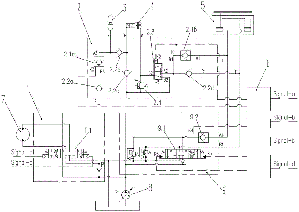
[0024] Below will combine concrete embodiment and appended figure 1 The present invention is described in further detail:

[0025]The method of recovering and utilizing the potential energy of the excavator arm, when the boom is lowered, the first stage of boosting is realized through control according to the area difference between the rodless cavity and the rod cavity of the boom cylinder, and then the second stage of boosting is realized by the booster cylinder , through the two-stage pressurization, the potential energy of the boom lowering is converted into high-pressure energy and stored in the accumulator; when the energy is released, the high-pressure oil stored in the accumulator is introduced into the oil inlet of the swing control valve by controlling, Then, the pressure oil in the accumulator is introduced into the swing motor through the swing control valve to drive the swing operation.

[0026] Preferably, the first stage of supercharging in the two-stage superc...


PUM


Abstract

The invention discloses a method and a control device for recycling potential energy of a movable arm of an excavator. When the movable arm descends, first-stage pressure boosting can be realized in a controlled manner according to difference between the area of a rodless cavity of an oil cylinder of the movable arm and the area of a rod cavity of the oil cylinder of the movable arm, then second-stage pressure boosting is realized via a pressure boosting cylinder, the potential energy generated during descending of the movable arm can be converted into high-pressure energy through the two stages of pressure boosting, and the high-pressure energy is stored in an energy accumulator; and when the energy is released, high-pressure oil stored in the energy accumulator is led into an oil inlet of a rotation control valve in a controlled manner, pressure oil in the energy accumulator is led into a rotation motor through the rotation control valve, and rotation operation can be carried out. By the method and the control device for recycling the potential energy of the movable arm of the excavator, the energy can be reused, designing, manufacturing and overall arrangement of the pressure boosting cylinder are facilitated, and the energy of the energy accumulator can be released and used.

Description

technical field [0001] The invention relates to a method for recycling the potential energy of a boom, in particular to a method for recycling the potential energy of a medium-to-large excavator arm, and also relates to a control device for realizing the method for recycling the potential energy of the excavator arm. Background technique [0002] Excavator, as a typical construction machinery with wide application, high energy consumption and poor emission, has the characteristics of periodicity and heavy working equipment. From the perspective of energy conversion, the excavator arm can be lowered under the action of gravity. If no descending resistance is provided, weightlessness will easily occur during the descent. In order to prevent weightlessness when the boom is lowered, it is necessary to make the boom cylinder form a certain back pressure. The usual method is to use the spool opening area of ​​the multi-way valve. Reduce the throttling and then flow back to the fue...

Claims


Application Information

Patent Timeline
Patent Type & Authority Patents(China)
IPC IPC(8): E02F3/43F15B21/14
Inventor 何清华许长飞郭勇郝鹏张新海张大庆唐中勇刘昌盛
Owner SUNWARD INTELLIGENT EQUIP CO LTD
Why Eureka
Try Eureka