Oil well casing pressure control device
A technology for control devices and oil wells, which is applied in wellbore/well valve devices, wellbore/well components, earthwork drilling and production, etc. It can solve the problems of heavy manual workload, inability to realize automatic control of casing pressure, and low efficiency. Achieve the effects of improving pump efficiency and system efficiency, reducing environmental pollution and potential safety hazards, and solving heavy manual workload
- Summary
- Abstract
- Description
- Claims
- Application Information
AI Technical Summary
Problems solved by technology
Method used
Image
Examples
Embodiment 1
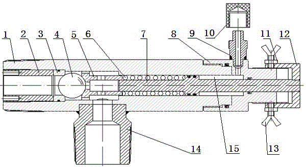
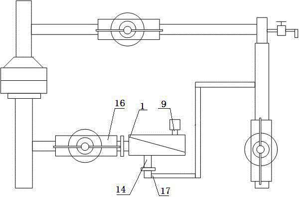
[0017] In order to overcome the problems of large manual workload and low efficiency in oil well casing pressure control in existing crude oil production, and the inability to realize automatic control of casing pressure, this embodiment provides a method such as figure 1 with figure 2 The shown oil well casing pressure control device includes a valve body 1, a pressure cap 2 is connected to the inside of the front end of the valve body 1, and a ball seat 3, a cut-off steel ball 4 and a steel ball push rod 5 are set inside the valve body 1, The ball seat 3 is connected with the pressure cap 2, the cut-off steel ball 4 is placed between the ball seat 3 and the steel ball push rod 5, and the inner side of the steel ball push rod 5 is set with a pressure regulating valve 7. A pressure regulating spring 6 is sleeved on the outside of the pressure valve 7, and the pressure regulating spring 6 is connected to the steel ball push rod 5. A tail cap 8 is connected to the outside of th...
Embodiment 2
[0021] This embodiment provides an oil well casing pressure control device, which includes a valve body 1, a pressure cap 2 is connected to the inside of the front end of the valve body 1, and a ball seat 3, a cut-off steel ball 4 and a steel ball are set inside the valve body 1. The push rod 5, the ball seat 3 is connected with the pressure cap 2, the cut-off steel ball 4 is placed between the ball seat 3 and the steel ball push rod 5, and the inside of the steel ball push rod 5 is set with a pressure regulating valve 7 , the outside of the pressure regulating valve 7 is sleeved with a pressure regulating spring 6, the pressure regulating spring 6 is connected with the steel ball push rod 5, and the outside of the tail of the valve body 1 is connected with a tail cap 8, and the tail cap 8 is a A pressure regulating interface 9 is connected to the side wall, and the pressure regulating interface 9 communicates with the pressure regulating chamber 15 of the valve body 1, and the...
Embodiment 3
[0024] This embodiment provides an oil well casing pressure control device, which includes a valve body 1, a pressure cap 2 is connected to the inside of the front end of the valve body 1, and a ball seat 3, a cut-off steel ball 4 and a steel ball are set inside the valve body 1. The push rod 5, the ball seat 3 is connected with the pressure cap 2, the cut-off steel ball 4 is placed between the ball seat 3 and the steel ball push rod 5, and the inside of the steel ball push rod 5 is set with a pressure regulating valve 7 , the outside of the pressure regulating valve 7 is sleeved with a pressure regulating spring 6, the pressure regulating spring 6 is connected with the steel ball push rod 5, and the outside of the tail of the valve body 1 is connected with a tail cap 8, and the tail cap 8 is a A pressure regulating interface 9 is connected to the side wall, and the pressure regulating interface 9 communicates with the pressure regulating chamber 15 of the valve body 1, and the...
PUM
 Abstract
Description
Claims
Application Information
 - R&D
- Intellectual Property
- Life Sciences
- Materials
- Tech Scout
- Unparalleled Data Quality
- Higher Quality Content
- 60% Fewer Hallucinations
Browse by: Latest US Patents, China's latest patents, Technical Efficacy Thesaurus, Application Domain, Technology Topic, Popular Technical Reports.
© 2025 PatSnap. All rights reserved.Legal|Privacy policy|Modern Slavery Act Transparency Statement|Sitemap|About US| Contact US: help@patsnap.com


