
Valve gear transmission apparatus of engine

A transmission and engine technology, applied in the direction of engine components, valve driving devices, machines/engines, etc., can solve problems such as engine reversal, damage, and cams are accidentally switched, and achieve the effect of preventing damage to operating parts

Inactive Publication Date: 2015-03-25
MAZDA MOTOR CORP
View PDF5 Cites 10 Cited by
  • Summary
  • Abstract
  • Description
  • Claims
  • Application Information

AI Technical Summary

Problems solved by technology

[0006] However, in an engine equipped with a valve train as described above, when the engine is turned off immediately after the crankshaft rotates, or when the engine is stopped, the engine may reverse due to the reaction force received by the cylinder piston in the compression stroke.
Therefore, in the valve trains of Patent Documents 1 and 2, when the engine reverses while the operating member is protruding, the end face cam of the reversed cam unit portion engages with the operating member, and the operating member moves the cam unit in the axial direction. , making it possible for the cam to be switched accidentally
[0007] especially in Figure 12 In the case of the shown valve train, when the engine reverse direction (rotation in the arrow Y direction) occurs while the operating member 132 is protruding, the operating member 132 may contact the step portion 123a of the end cam 123 of the cam unit unit 120. damaged by collision

Method used


Image

  • Valve gear transmission apparatus of engine
  • Valve gear transmission apparatus of engine
  • Valve gear transmission apparatus of engine

Examples


Embodiment Construction

[0032] Hereinafter, embodiments of the present invention will be described by taking a valve train of a four-cylinder, four-valve DOHC engine as an example.

[0033] [Outline structure of valve train]

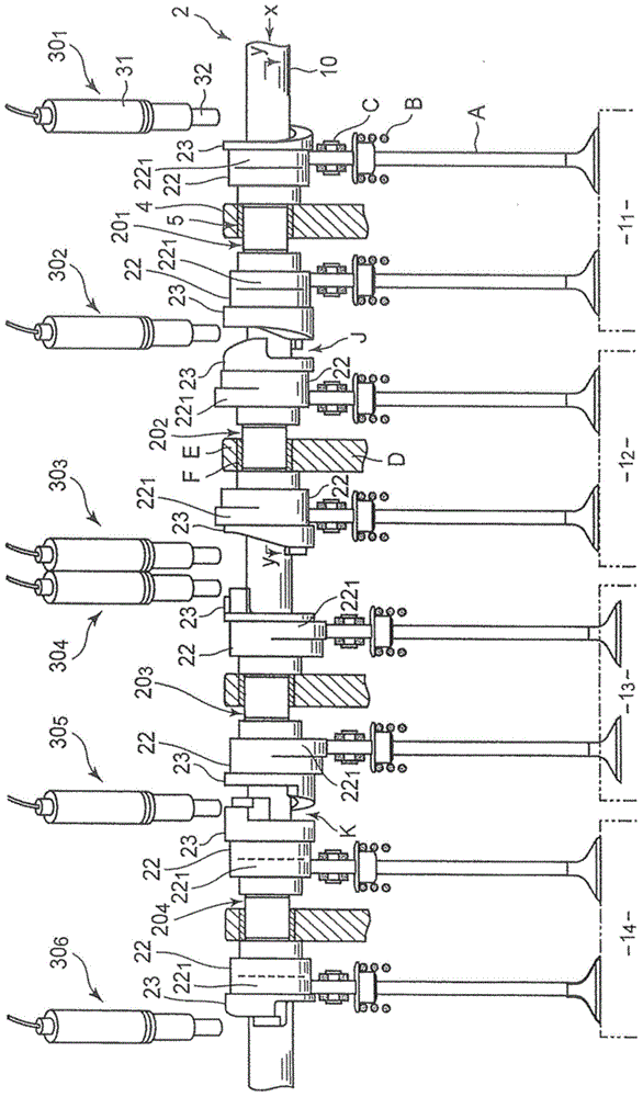
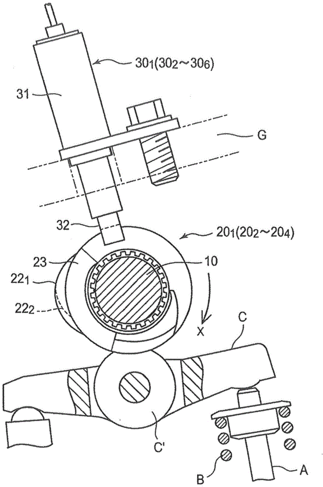
[0034] figure 1 The configuration of the exhaust side of the valve train according to the present embodiment is shown. On the unshown cylinder head, for the first to fourth cylinders 1 1 ~1 4 Each has two exhaust valves A...A in total. The valve transmission device used to drive these exhaust valves A...A includes: return spring B...B, which exerts a force in the closing direction on the exhaust valve A...A; camshaft 2, which is arranged on the upper part of the cylinder head, The arms C...C overcome the force of the return springs B...B and drive the exhaust valves A...A in the opening direction; the operating mechanism 30 is arranged above the camshaft 2 .

[0035] The camshaft 2 is rotatably supported by the bearings F...F of the cylinders 1 on the cylinder head, and i...


PUM


Abstract

A valve gear transmission apparatus of an engine, wherein an operation mechanims for switching a cam part of a cam unit part is provided with: an end operation part arranged on an axial end side of a cam unit part; and an actuator capable of driving the end operation part so that the end operation part is moved between an operation position and a back position. The end operation part is arranged in a manner that: when the end operation part moves to the operation part, the end operation part is engaged with a lift part of the cam at one end side so that the cam unit part moves to the other axial side for switching the cam part which opens and cloths the valve gear. The cam unit part is provided with a reversion reset inclined part which is positioned at a rotating delay side relative to a maximum lift part of a end side cam engaged with the end operation part and is formed in a manner that the more far away from an external peripheral surface of the rotating delay side, the less is the radius, so that the cam unit can be prevented from being switched or the operation part is free from bieng damaged due to reversion of the engine.

Description

technical field [0001] The present invention relates to a valve train for an engine used in a vehicle, and more particularly to a valve train capable of switching a cam for opening and closing a valve, and belongs to the technical field of a valve train for an engine. Background technique [0002] As a valve transmission device of an engine, a device is known in which a plurality of cams are provided for one valve, the shapes of the tips of these cams are different from each other, and by selecting the cam for opening and closing the valve among these cams, it is possible to correspond to the engine. The operating state of the valve is used to switch the opening degree or opening and closing period of the intake and exhaust valves. [0003] For example, Japanese Patent Laid-Open Publication No. 2013-083202 (hereinafter referred to as Patent Document 1) and U.S. Patent Publication No. 2011 / 0226205A1 (hereinafter referred to as Patent Document 2) disclose valve trains that inc...

Claims


Application Information

Patent Timeline
Patent Type & Authority Applications(China)
IPC IPC(8): F01L13/00F01L1/04
CPCF01L13/0036F01L2013/0052F01L2820/031F01L1/08F01L1/344
Inventor 小谷敏正高木章智羽原俊辅柏原尚志
Owner MAZDA MOTOR CORP
Learn More