Ball cage type constant velocity universal joint

A constant velocity universal joint and ball cage technology, which is applied in the field of auto parts, can solve the problems of short durability life of ball cage type constant velocity universal joints, short durability life, ballway wear, etc., achieve balanced wear and improve durability The effect of life and accelerated wear rate

Active Publication Date: 2015-03-25
SHANGHAI GKN DRIVE SYST
View PDF8 Cites 1 Cited by
  • Summary
  • Abstract
  • Description
  • Claims
  • Application Information

AI Technical Summary

Problems solved by technology

The part of the ballway on the side where the torsional pressure is often applied is severely worn and the durability is short, while the part of the ballway on the side where the torsional pressure is not often applied is slightly worn and the durability is long, which makes the overall durability of the cage type constant velocity universal joint shorter lifespan

Method used


Image

  • Ball cage type constant velocity universal joint
  • Ball cage type constant velocity universal joint
  • Ball cage type constant velocity universal joint

Examples


Embodiment Construction

[0047] Embodiments of the present invention are described below through specific examples, and those skilled in the art can easily understand other advantages and effects of the present invention from the content disclosed in this specification. The present invention can also be implemented or applied through other different specific implementation modes, and various modifications or changes can be made to the details in this specification based on different viewpoints and applications without departing from the spirit of the present invention.

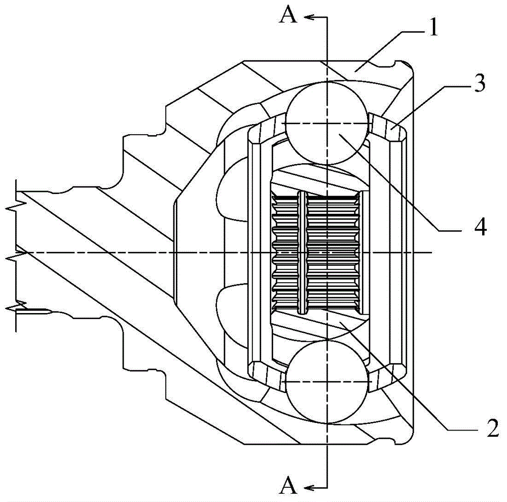
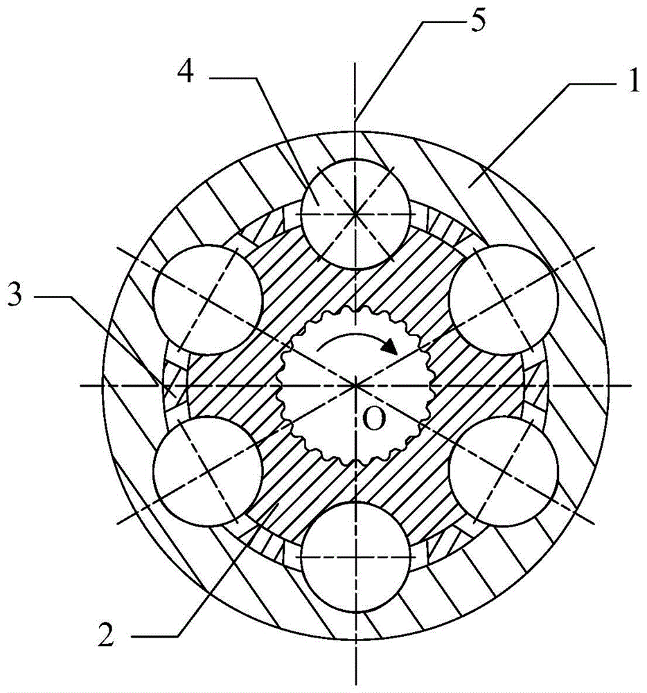
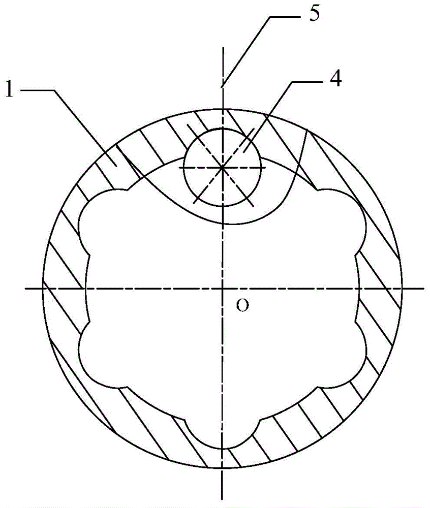
[0048] see Figure 1 to Figure 8 . It should be noted that the diagrams provided in this embodiment are only schematically illustrating the basic idea of ​​the present invention, and only the components related to the present invention are shown in the diagrams rather than the number, shape and shape of the components in actual implementation. Dimensional drawing, the type, quantity and proportion of each component can be changed arb...


PUM


Abstract

The invention provides a ball cage type constant velocity universal joint. An external ball way deflection long shaft intersects with a center line at the ball center of a rolling body to form an external ball way deflection angle delta 1, and the deflection direction of delta 1 relative to the center line is opposite to the direction of torque frequently exerted on an external ball way. The length of a long external ball way arc on the same side of the external ball way deflection long shaft with delta 1 is larger than the length of a short external ball way arc on the other side. An internal ball way deflection long shaft intersects with the center line at the ball center of the rolling body to form an internal ball way deflection angle delta 2, and the deflection direction of delta 2 relative to the center line is opposite to the direction of torque frequently exerted on an internal ball way. The length of a long internal ball way arc on the same side of the internal ball way deflection long shaft with delta 2 is larger than the length of a short internal ball way arc on the other side. The long external ball way arc or the long internal ball way arc scatters the torque pressure, the torque pressure stress subjected by the side, frequently subjected by the torque pressure, on the ball ways is reduced, the abrasion degree of the ball ways can be balanced, and the service life of the ball cage type constant velocity universal joint is prolonged.

Description

technical field [0001] The invention relates to the technical field of auto parts, in particular to a ball cage type constant velocity universal joint. Background technique [0002] A high-performance constant velocity universal joint shaft assembly for a passenger car usually consists of a fixed universal joint, a sliding universal joint, and an intermediate shaft connected between the universal joints. The high-performance constant velocity universal drive shaft assembly requires not only stable power transmission, but also reliable strength and durability. [0003] At present, most of the high-performance constant velocity universal drive shaft assemblies of passenger cars adopt ball cage type constant velocity universal joints, including ball cage type constant velocity fixed universal joints and ball cage type constant velocity sliding universal joints. Festival. The conventional spherical cage type constant velocity universal joint is composed of an outer star wheel,...

Claims


Application Information

Patent Timeline
Patent Type & Authority Applications(China)
IPC IPC(8): F16D3/22
Inventor 朱卓选
Owner SHANGHAI GKN DRIVE SYST
Why Eureka
Try Eureka