Stage lighting driving system and stage lighting using the system

A driving system and lighting technology, applied in lighting applications, devices used in theaters and circuses, parts of lighting devices, etc., can solve the problems of increased transportation costs, complicated installation, and occupying more space, and achieve internal structure The effect of large space, reduced manufacturing cost, and reduced internal space

Active Publication Date: 2017-08-11
GUANGZHOU HAOYANG ELECTRONICS CO LTD
View PDF19 Cites 0 Cited by
  • Summary
  • Abstract
  • Description
  • Claims
  • Application Information

AI Technical Summary

Problems solved by technology

[0003] However, in the prior art, each optical element bracket in the stage lamp is generally driven by each motor independently, that is, each optical element bracket is connected to a different motor respectively, although such an arrangement can realize the operation of each optical element bracket. It is used in operation, but there are the following defects: (1) It needs to be equipped with multiple motors and corresponding drive installation structures, which greatly increases the manufacturing cost of stage lamps to a certain extent, and the installation is complicated; (2) Each optical component bracket needs Equipped with the corresponding drive installation structure, it needs to take up a lot of space, so that the internal space of the stage lamp must be enlarged, which makes the lamp bulky and heavy, increases the transportation cost, and is inconvenient to use; A certain space design, otherwise there will be interference phenomenon, which will cause the use of each optical component holder to affect each other

Method used


Image

  • Stage lighting driving system and stage lighting using the system
  • Stage lighting driving system and stage lighting using the system
  • Stage lighting driving system and stage lighting using the system

Examples


Embodiment 1

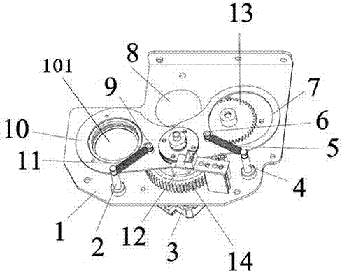
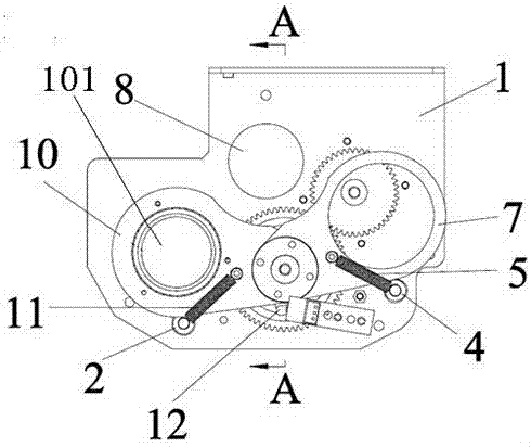
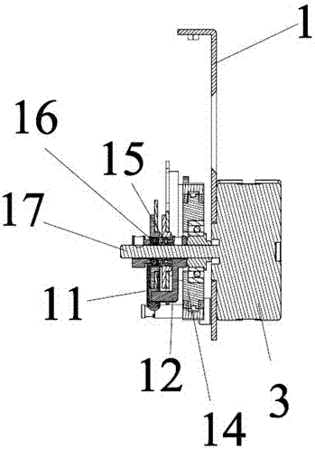
[0026] refer to Figure 1 to Figure 6 , the stage lighting driving system includes a support 1, a driving motor 3, two optical element brackets 10 and an optical element bracket 7 (more optical element brackets can also be provided as required), the optical element bracket 10 and the optical element bracket 7 are respectively provided with a prism 101 and an atomizing mirror (not shown), and the prism 101 is rotatably mounted on the academic element bracket 10; the support 1 is provided with a light hole 8, and the two The optical element brackets 10 (and 7) are respectively arranged on both sides of the light-through hole 8; the drive motor 3 is installed on the support 1, and each optical element bracket 10 (and 7) passes through the bearing (or slip ring) 15 (and 16) are rotatably sleeved on the rotating shaft 17 of the driving motor 3, and the optical element brackets are arranged in staggered layers; the rotating shaft 17 of the driving motor 3 is fixedly connected with a...

Embodiment 2

[0029] This embodiment is similar to Embodiment 1, the difference is that the optical elements on the optical element holder 10 and the optical element holder 7 are all prisms 101, and the prisms 101 can be rotatably mounted on the optical element holders 10 and 7 , the rotation gears connected with the prism 101 are all meshed with the driven wheel 14 . The working principle of the stage lighting driving system and the prism rotation in this embodiment are similar to those in the first embodiment.

Embodiment 3

[0031] This embodiment is similar to Embodiment 1, and the difference is that the optical elements on the two optical element holders 10 and the optical element holder 7 are all atomized mirrors, and the two atomized mirrors are respectively non-rotatably mounted on the two optical element holders In 10 and 7, since the two atomized mirrors do not need to rotate, this embodiment can omit the rotation drive assembly for driving the rotation of the optical element. The working principle of the stage lighting driving system in this embodiment is similar to that in Embodiment 1.


PUM


Abstract

The invention relates to the technical field of stage lighting, and particularly relates to a driving system for stage lamps. The driving system comprises a base, a driving motor and at least two optical element brackets and optical elements, wherein the optical elements are mounted on the optical element brackets; the driving motor is arranged on the base; the base is provided with light holes; the optical element brackets sleeve a rotating shaft of the driving motor in a rotatable manner; a pushing component is fixedly connected onto the rotating shaft of the driving motor, and is used for pushing the optical element brackets to move; a reset component is arranged on each optical element bracket. The driving system simply needs one set of motor driving structure to drive a plurality of optical element brackets, can greatly reduce the manufacturing cost, is simple and reasonable to mount, and can greatly reduce occupied internal space meanwhile, so that internal structural space of the stage lamps is enlarged, and the using effect of the lamps is improved.

Description

technical field [0001] The utility model relates to the technical field of stage lights, in particular to a driving system for stage lights and a stage light using the system. Background technique [0002] In the field of stage lighting, in order to shape various stage lighting effects, it is often necessary to use various optical components in stage lighting to process the beam, for example, using prisms to split the beam or make the beam disperse, and using atomized lenses to treat the beam Carry out fogging and soft light treatment. [0003] However, in the prior art, each optical element bracket in the stage lamp is generally driven by each motor independently, that is, each optical element bracket is connected to a different motor respectively, although such an arrangement can realize the operation of each optical element bracket. It is used in operation, but there are the following defects: (1) It needs to be equipped with multiple motors and corresponding drive insta...

Claims


Application Information

Patent Timeline
Patent Type & Authority Patents(China)
IPC IPC(8): F21V14/00
CPCF21V14/00F21V14/06F21W2131/406
Inventor 蒋伟楷
Owner GUANGZHOU HAOYANG ELECTRONICS CO LTD
Why Eureka
Try Eureka