Vibration detection device and method for fixed support plate at both ends based on optical fiber displacement measuring instrument

A technology of displacement measurement and vibration detection, which is applied in the direction of measuring devices, measuring ultrasonic/sonic/infrasonic waves, instruments, etc., can solve the problems of application limitations, large measurement noise of acceleration sensors, and changing the structural characteristics of wall panels, etc., and achieve a wide frequency range, Fast dynamic response and high measurement accuracy

Inactive Publication Date: 2017-06-06
SOUTH CHINA UNIV OF TECH
View PDF5 Cites 0 Cited by
  • Summary
  • Abstract
  • Description
  • Claims
  • Application Information

AI Technical Summary

Problems solved by technology

[0003] In order to suppress the flutter of the wallboard, it is necessary to detect the amount of vibration first. However, in the prior art, contact sensors are generally used to measure it, such as the detection of pasted piezoelectric ceramics, or the detection of installed acceleration sensors. The additional mass generated by the plate will change the structural characteristics of the wall plate. At the same time, the piezoelectric ceramic material is a brittle material, and the strength and fatigue life of the material are affected by the ambient temperature, so the application is subject to certain restrictions. The measurement noise of the acceleration sensor is relatively large. This requires filtering of the vibration signal

Method used


Image

  • Vibration detection device and method for fixed support plate at both ends based on optical fiber displacement measuring instrument
  • Vibration detection device and method for fixed support plate at both ends based on optical fiber displacement measuring instrument
  • Vibration detection device and method for fixed support plate at both ends based on optical fiber displacement measuring instrument

Examples


Embodiment

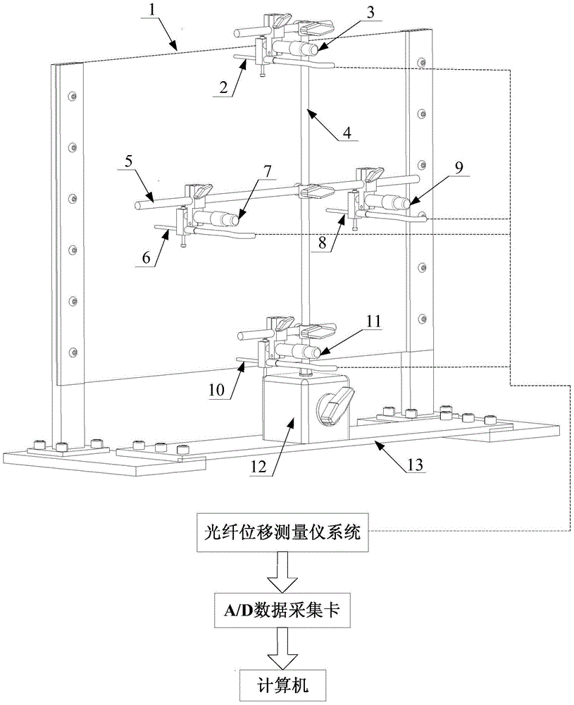
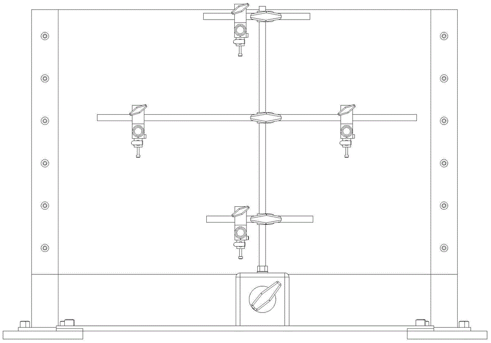
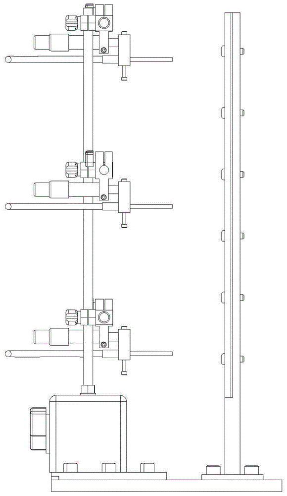
[0043] Such as figure 1 , figure 2 , image 3 and Figure 4 As shown, a vibration detection device based on an optical fiber displacement measuring instrument with fixed supports at both ends, including a flexible board body part and a vibration detection part.

[0044]The main part of the flexible board includes a flexible board 1, a magnetic base 12, a large base 13, an optical fiber probe and a micrometer. Both ends of the flexible board 1 are fixed by mechanical clamping devices, and the magnetic base 12 is installed on the large base 13. Above, the fiber optic probe is installed directly in front of the flexible board 1 through the horizontal bracket 5 and the vertical bracket 4, the vertical bracket 4 and the horizontal bracket 5 are cross-shaped and fixed, and the horizontal bracket 5 can be placed on the vertical bracket 4, specifically, the first and fourth fiber optic probes 2 and 10 are installed on the vertical support 4, and the second and third fiber optic pr...


PUM


Abstract

The invention discloses a two-end fixing support plate vibration detection device and method based on an optical fiber displacement measurement instrument. The two-end fixing support plate vibration detection device comprises a flexible plate body part and a vibration detection part. The flexible plate body part comprises a flexible plate, a magnetic base, an optical fiber probe and a micrometer, the two ends of the flexible plate are fixed through mechanical clamping devices, the optical fiber probe is installed right ahead the flexible plate through a horizontal support and a vertical support, the distance between the optical fiber probe and the flexible plate is adjusted through the micrometer, and the vertical support is installed on the magmatic base. The vibration detection part comprises an optical fiber displacement measurement instrument system, an A / D data collecting card and a computer, vibration signals of the optical fiber probe are collected through the optical fiber displacement measurement instrument system, processed by the A / D data collecting card and transmitted to the computer, and the computer obtains low-order mode vibration of two-end fixing support plates through decoupling to be used for vibration analysis or control. By means of the two-end fixing support plate vibration detection device and method, decoupling of the two-end fixing support plates on low-order mode vibration detection is achieved in a non-contact detection mode.

Description

technical field [0001] The invention relates to the field of vibration detection of two-end fixed support plates, in particular to a vibration detection device and method for two-end fixed support plates based on an optical fiber displacement measuring instrument. Background technique [0002] With the rapid development of modern aircraft technology, the speed of aircraft is becoming more and more high-sonic or hypersonic. In order to reduce the structural weight, more thin-walled structures are used in the structural design of the new generation of high-speed aircraft. Due to the light weight and small modal damping of the thin-walled structure, coupled with the aerodynamic influence of high-speed airflow, it is easy to cause structural vibration or wall panels. flutter. Panel flutter refers to a self-excited vibration phenomenon of the panel structure (such as wing skin) of high-speed aircraft in supersonic airflow. When a high-speed aircraft vibrates due to uncertain di...

Claims


Application Information

Patent Timeline
Patent Type & Authority Patents(China)
IPC IPC(8): G01H9/00
Inventor 邱志成谢凌波
Owner SOUTH CHINA UNIV OF TECH
Why Eureka
Try Eureka