
Device and method for vibration detection and control of parallel platform based on laser displacement sensor

A laser displacement and vibration detection technology, applied in measurement devices, program-controlled manipulators, instruments, etc., can solve the problems of high noise measurement of accelerometers, application limitations, and changing system structural characteristics.

Active Publication Date: 2016-07-06
SOUTH CHINA UNIV OF TECH
View PDF5 Cites 2 Cited by
  • Summary
  • Abstract
  • Description
  • Claims
  • Application Information

AI Technical Summary

Problems solved by technology

[0003] In order to control the residual vibration of the moving platform of the parallel robot, it is first necessary to detect the amount of vibration. In the prior art, contact sensors are generally used to measure it, such as using mounted acceleration sensors for detection, or using pasted piezoelectric ceramic sheets for detection, etc. , these methods will generate additional mass on the flexible passive rod or moving platform, which will change the structural characteristics of the system. At the same time, the measurement noise of the acceleration sensor is relatively large, which requires filtering of the vibration signal, and the piezoelectric ceramic material is a brittle material. The strength and fatigue life are affected by the ambient temperature, so the application is subject to certain restrictions

Method used


Image

  • Device and method for vibration detection and control of parallel platform based on laser displacement sensor
  • Device and method for vibration detection and control of parallel platform based on laser displacement sensor
  • Device and method for vibration detection and control of parallel platform based on laser displacement sensor

Examples


Embodiment 1

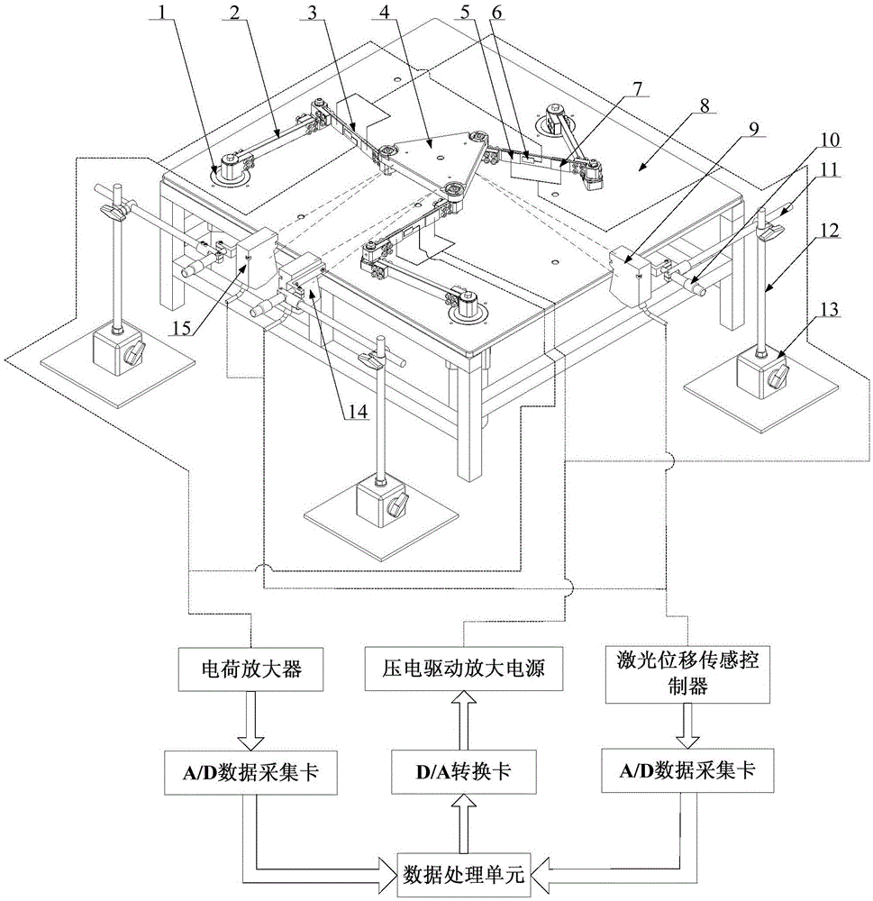
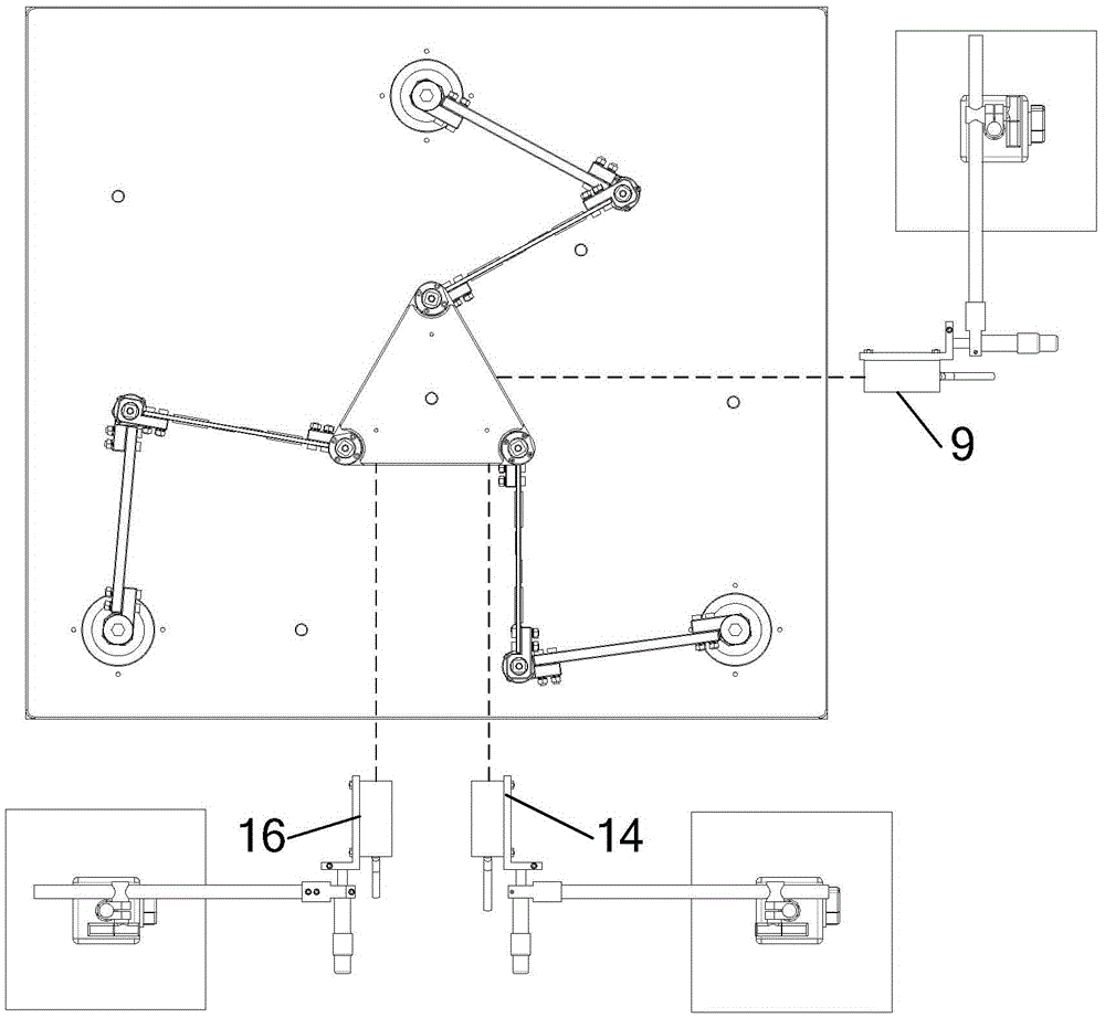
[0040] For the structure of the laser displacement sensor-based parallel platform vibration detection and control device described in this embodiment, see figure 1 , the device includes a parallel platform body unit, a vibration detection unit, and a vibration control unit. The above-mentioned units will be described in detail below with reference to the figures.

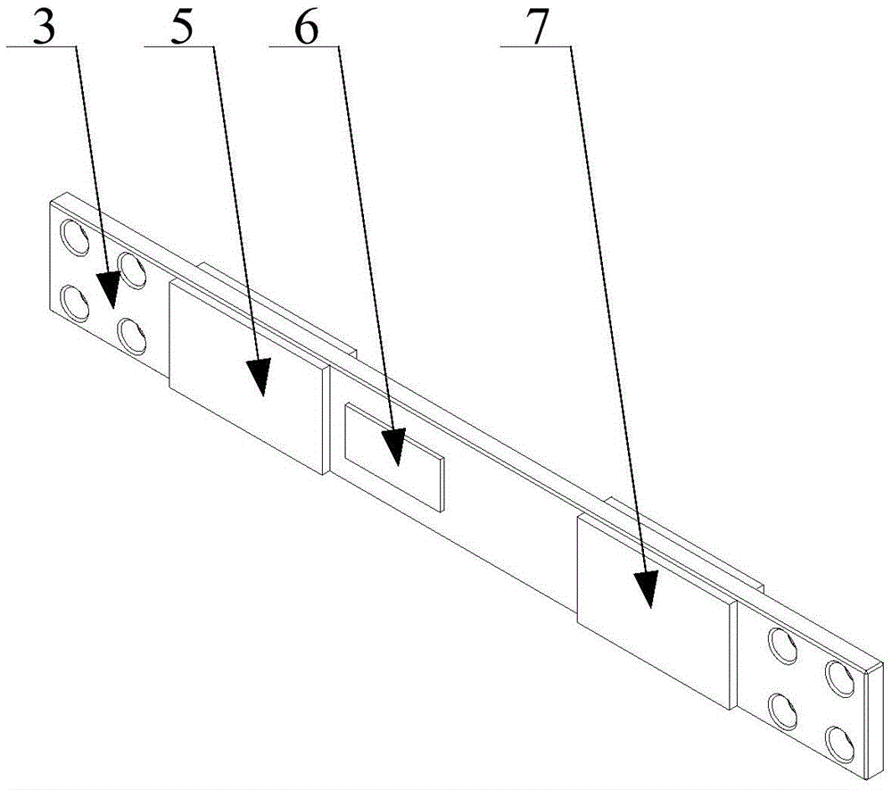
[0041] The parallel platform body unit includes a moving platform 4, a static platform 8 and three parallel branches, and the moving platform 4 is an equilateral triangle. Each parallel branch includes a motor 1, an active rod 2 and a driven flexible rod 3. The motor 1 in this embodiment is an Yaskawa servo motor, which is respectively installed on the edge of the static platform 8, and each motor shaft end is connected to an active rod 2. The other end of each active rod 2 is connected to a driven flexible rod 3 through a rotating shaft, and the other end of each driven flexible rod 3 is connected to a moving platf...


PUM


Abstract

The invention discloses a laser displacement sensor based parallel platform vibration detection control device and method. The device comprises a parallel platform body unit, a vibration detection unit and a vibration control unit. The parallel platform body unit comprises a movable platform, a static platform and three parallel branches. Each parallel branch comprises a motor, a driving rod and a driven flexible rod which are connected successively. A plurality of piezoelectric ceramic piece drivers are pasted on the driven flexible rods. Three laser detection heads are arranged on the periphery of the static platform to be used for detecting the translation displacement and the rotation angle of the movable platform in the horizontal direction. The motors drive the driving rods and the driven flexible rods to locate the movable platform behind the target position, the movable platform has residual vibration, the laser detection head detects vibration signals of the movable platform, the vibration control unit applies the control quantity to the piezoelectric ceramic piece drivers, and accordingly, driving control over the residual vibration of the parallel platforms is achieved. The device and the method have the advantages of being high in measurement accuracy and sampling frequency and quick in dynamic response.

Description

technical field [0001] The invention relates to the research field of positioning vibration detection and control of a flexible parallel platform, in particular to a vibration detection and control device and method for a parallel platform based on a laser displacement sensor. Background technique [0002] A parallel robot is a robot that includes a parallel mechanism. The parallel mechanism is that the end effector with several degrees of freedom is connected to the fixed base through two or more independent motion branch chains. A parallel robot consists of two platforms, namely a dynamic platform and a static platform (also known as a fixed platform). The static platform is fixed on the base or connected to the end effector of another robot, and the dynamic platform moves relative to the static platform. The two platforms are connected by two or more branch chains. It has two or more degrees of freedom, and the drives are generally distributed on one end connected to the...

Claims


Application Information

Patent Timeline
Patent Type & Authority Patents(China)
IPC IPC(8): B25J9/00G01H9/00
Inventor 张宪民谢凌波邱志成
Owner SOUTH CHINA UNIV OF TECH
Learn More