A Velocity Modeling Method Based on RTM Imaging

A velocity modeling and velocity model technology, applied in the field of geophysical exploration, can solve the problems that the velocity model cannot be effectively added to the prior information of well logging data, and the velocity model establishment process is difficult to control, so as to improve the imaging quality and accuracy

Active Publication Date: 2017-06-20
CHINA PETROLEUM & CHEM CORP +1
View PDF7 Cites 0 Cited by
  • Summary
  • Abstract
  • Description
  • Claims
  • Application Information

AI Technical Summary

Problems solved by technology

[0003] At present, the establishment of RTM-based velocity models relies on commercial software, making the establishment of the velocity model difficult to control
Especially in blocks with rich logging data, it is impossible to effectively add prior information such as logging data to improve the velocity model

Method used


Image

  • A Velocity Modeling Method Based on RTM Imaging
  • A Velocity Modeling Method Based on RTM Imaging
  • A Velocity Modeling Method Based on RTM Imaging

Examples


no. 1 example

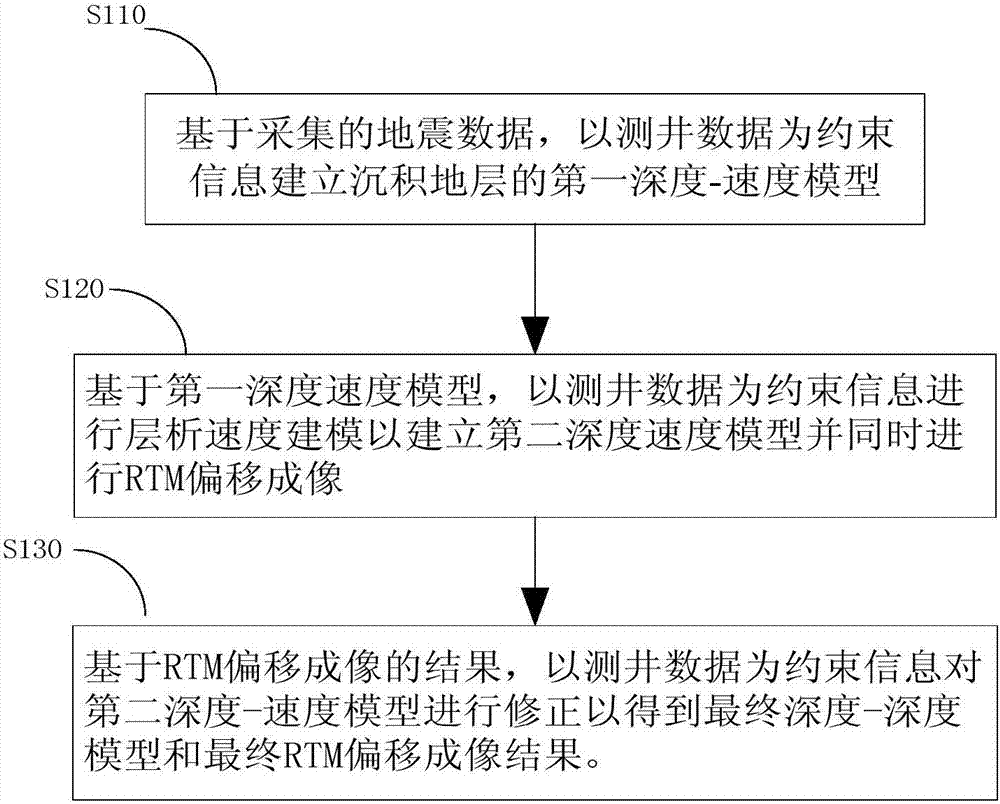
[0045] figure 1 is a method flow chart according to an embodiment of the present invention, refer to below figure 1 Each step of the present invention will be described in detail.

[0046] In step S110, the seismic data of the underground sedimentary stratum is obtained by seismic exploration technology, the logging data of the sedimentary stratum is obtained by well logging technology, and the first depth-velocity model of the sedimentary stratum is established with the logging data as constraint information.

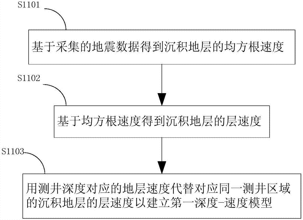
[0047] The logging data here includes the logging depth obtained by the acoustic logging technology and the formation velocity corresponding to each logging depth. This step can be further divided into figure 2 The following steps are shown.

[0048] In step S1101, velocity analysis is performed on the acquired seismic data to obtain the root mean square velocity of the sedimentary formation. The root mean square velocity is used to characterize the overall veloci...

no. 2 example

[0060] like Figure 5 , Image 6 , Figure 7 and Figure 8 What is shown is to use a specific embodiment of the present invention to illustrate the effect of applying the method described in the present invention.

[0061] like Figure 5 Shown is a schematic diagram of the logging constraint data and the initial layer velocity field, the horizontal axis represents the position of the common center point, and the vertical axis represents the formation depth. As shown in the figure, in some areas inside the sedimentary formation, the layer velocity of the formation in this area can be obtained through logging technology. The formations are divided into different blocks according to different formation velocities, and the formations corresponding to different formation velocities are shown in different gray levels in the figure, where different gray levels only indicate that the formation velocities between adjacent formations are different, not It specifically indicates the...


PUM


Abstract

The invention discloses a velocity modeling method based on RTM imaging. The velocity modeling method includes the following steps that based on collected seismic data, a first depth-velocity model of a sedimentary strata is established with log data as constraint information; based on the first depth-velocity model, chromatography velocity modeling is performed with the log data as the constraint information so that a second depth-velocity model can be established, and RTM imaging can be performed; based on a result of RTM imaging, the second depth-velocity model is corrected with the log data as the constraint information so that a final depth-velocity model and a final RTM imaging result can be obtained. While high-precision chromatography velocity modeling is kept, the log data and other prior information are effectively added, the precision of velocity modeling is improved for complex fault blocks, and the quality of RTM imaging is improved.

Description

technical field [0001] The invention relates to the technical field of geophysical exploration, in particular to a velocity model method based on RTM (reverse time migration) technology. Background technique [0002] RTM (reverse time migration) imaging technology is currently the latest geophysical exploration technology, mainly divided into post-stack reverse time migration and pre-stack reverse time migration, and is currently the best method to achieve migration imaging. [0003] At present, the establishment of RTM-based velocity models relies on commercial software, which makes the establishment of the velocity model difficult to control. Especially in blocks with abundant well logging data, it is impossible to effectively add prior information such as well logging data to improve the velocity model. [0004] Based on the above situation, there is an urgent need for a velocity modeling method based on RTM imaging technology and logging data. Contents of the inventio...

Claims


Application Information

Patent Timeline
Patent Type & Authority Patents(China)
IPC IPC(8): G01V1/40
Inventor 郭廷超
Owner CHINA PETROLEUM & CHEM CORP
Why Eureka
Try Eureka