Display device and control method and control circuit thereof

A display device and control circuit technology, applied in the direction of static indicators, instruments, etc., can solve the problems of high development and verification costs, reliability problems of contact terminals, etc., and achieve low development costs, reduce shutdown surge current, and flexible applications Effect

Active Publication Date: 2015-03-25
NANJING CEC PANDA LCD TECH
View PDF8 Cites 21 Cited by
  • Summary
  • Abstract
  • Description
  • Claims
  • Application Information

AI Technical Summary

Problems solved by technology

However, when the panel size is larger and the resolution is higher, the VGH voltage will cause a large IGH current (Surge current) when the tidal circuit is activated during shutdown. This large IGH current needs to flow through the contact terminal and the glass wiring. , IGH high current may cause reliability problems of all contact terminals on the path
[0005] At present, most of the solutions to the shutdown surge current problem are solved by changing the internal structure of the Driver IC, or adding lines on the glass substrate, and modifying the WOA wiring. The development and verification costs are relatively high.

Method used


Image

  • Display device and control method and control circuit thereof
  • Display device and control method and control circuit thereof
  • Display device and control method and control circuit thereof

Examples


Embodiment 1

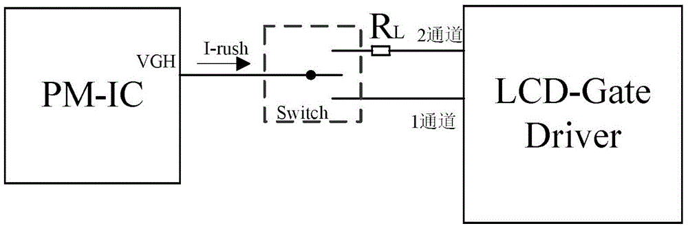
[0049] Figure 4 It is a schematic structural diagram of the control circuit of the display device according to Embodiment 1 of the present invention. Such as Figure 4 As shown, Embodiment 1 of the present invention provides a display device control circuit, which is set in the drive circuit of the display device. The drive circuit includes a power module PMIC and a gate driver Gate Driver connected to the power module. The display The device control circuit includes: a current limiting module RL, which is used to limit the instantaneous current Irush output by the power supply device when the gate driver outputs multiple gate signals at the same time. Preferably, the current limiting module RL is a resistor The switch control module is used to detect the voltage signal output by the power supply module. When the liquid crystal display panel is working normally, the switch control module directly provides the voltage signal output by the power supply device to the gate drive...

Embodiment 2

[0055] Figure 5 It is a schematic structural diagram of the control circuit of the display device according to Embodiment 2 of the present invention. Such as Figure 5 As shown, Embodiment 2 of the present invention provides a display device control circuit, which is set in the drive circuit of the display device. The drive circuit includes a power module PMIC and a gate driver Gate Driver connected to the power module. The display The device control circuit includes: a current limiting module RL, which is used to limit the instantaneous current Irush output by the power supply device when the gate driver outputs multiple gate signals at the same time. Preferably, the current limiting module RL is a resistor The switch control module is used to detect the voltage signal output by the power supply module. When the liquid crystal display panel is working normally, the switch control module directly provides the voltage signal output by the power supply device to the gate drive...


PUM


Abstract

The invention discloses a display device for eliminating shutdown ghost shadows and a control method and a control circuit of the display device. The control method of the display device is used for eliminating the shutdown ghost shadows of the display device and comprises the steps that voltage signals output by a power module are detected, and when a shutdown operation is executed, a switching circuit is arranged to control the output voltage signals of the power module to be supplied to a grid electrode driver through a current-limiting module. The display device and the control circuit of the display device can achieve the purpose of reducing shutdown surging current by adopting a simple circuit structure that a switch control module and the current-limiting module are connected in parallel, product cost is low and application is flexible.

Description

technical field [0001] The invention relates to the field of display technology, in particular to a display device for eliminating residual image after shutdown, a control method and a circuit thereof. Background technique [0002] figure 1 It is an equivalent circuit of a thin film transistor liquid crystal display in the prior art. Such as figure 1 As shown, a (m)x(n) matrix thin film transistor liquid crystal display includes: source wiring 100, the source signal of the thin film transistor 102; With the off voltage, the drain of the thin film transistor 102 is connected to the liquid crystal pixel 103 . [0003] When the panel displays a white picture, the charge of the liquid crystal pixel 103 is charged to the maximum. At this time, the gate wiring 101 is connected to the gate closing voltage (VGL), so that the thin film transistor is in an off state, and the internal charge of the liquid crystal pixel 103 has almost no leakage current. Ioff, so that the panel can ...

Claims


Application Information

Patent Timeline
Patent Type & Authority Applications(China)
IPC IPC(8): G09G3/36
Inventor 张瑞斌史可为
Owner NANJING CEC PANDA LCD TECH
Why Eureka
Try Eureka