Power supply seamless switching device and method of electrified railway traction substation

A technology for traction substations and electrified railways, applied in circuit devices, electrical components, emergency power supply arrangements, etc. The effect of flexible scheduling of maintenance time and improving work efficiency

Active Publication Date: 2016-09-07
NARI NANJING CONTROL SYST
View PDF6 Cites 9 Cited by
  • Summary
  • Abstract
  • Description
  • Claims
  • Application Information

AI Technical Summary

Problems solved by technology

[0004] 1. The fulfillment time of the maintenance plan depends on the "skylight" of the catenary, which is not flexible. Some traction stations "skylight" are arranged in the early morning, which affects the normal work and rest of maintenance personnel;
[0005] 2. Affected by weather and other factors, the maintenance "skylight" will be canceled temporarily, and only the next maintenance "skylight" can be applied for. The maintenance personnel sometimes cannot complete the maintenance task after going back and forth several times
The difficulty of switching the main power also often affects the maintenance of the 110 (220) kV line of the public power grid company. Sometimes the power supply side protection is directly activated to force the power supply to switch, which brings great safety hazards to the traction power supply;
[0006] 3. Due to the time limit of tens of minutes for repairing the "skylight", if the spacer of the backup power supply fails, it may not be possible to switch to the backup power supply in a short time, affecting the normal power supply of the railway

Method used


Image

  • Power supply seamless switching device and method of electrified railway traction substation
  • Power supply seamless switching device and method of electrified railway traction substation
  • Power supply seamless switching device and method of electrified railway traction substation

Examples


Embodiment

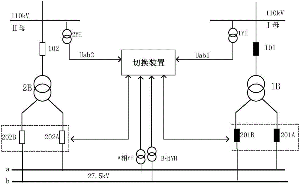
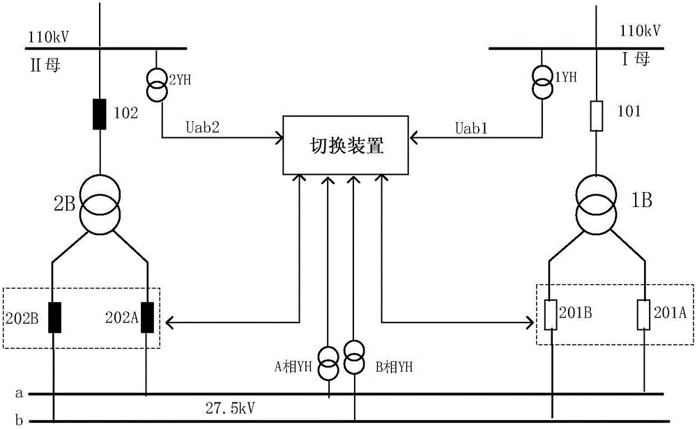
[0054] refer to figure 1 and figure 2 , the present invention uses a seamless switching device to access 4 voltages in electrified railway traction stations and substations, including: 27.5kV bus a, bus b two-phase voltage, 110kV bus I voltage one, 110kV bus II voltage one ; 4-way switch position signals: 201A and 201B switch normally closed auxiliary contacts on the low-voltage side of main transformer 1B, and switch normally closed auxiliary contacts on the main transformer 2B low-voltage side 202A and 202B. Not only can be applied to figure 1 mode of operation, and can be applied to figure 2 The operation mode, the two operation modes are symmetrical, and the mutual switching between the two operation modes is realized.

[0055] The present invention has the function of automatically identifying the current operating mode of the traction substation. Once a certain operating mode is recognized, it will automatically charge and make preliminary preparations for switching...


PUM


Abstract

The invention discloses a power supply seamless switching device and method of an electrified railway traction substation. Four paths of voltages, namely two-phase voltages of buses a and b of a contact network and voltages of a bus I and a bus II of a power supply, and four switching position signals, namely switches 201A and 201B of a low-voltage side of a main transformer 1B and switches 202A and 202B of a low-voltage side of a main transformer 2B are accessed to the switching device. During application, the current running mode of the traction substation is identified according to access quantity, automatic charging is achieved to prepare for switching if the running mode is normal, and discharging is performed to lock a switching function if the running mode is abnormal; three switching modes of parallel automatic switching, parallel semi-automatic switching and series switching can be performed; an optimal switching-on mode can be selected according to a real-time relation between the bus voltages of the power supply and the bus voltages of the contact network during switching on; and six modes of parallel rapid switching, rapid switching, same-phase lead phase angle switching, same-phase lead time switching, residual voltage switching and long delay switching can be performed, and uninterruptible power supply switching of two power supplies of the electrified railway traction substation can be achieved.

Description

technical field [0001] The invention relates to the technical field of electrified railway power supply, in particular to an electrified railway traction substation power supply seamless switching device and method. Background technique [0002] At present, the development of my country's electrified railway industry is advancing by leaps and bounds. Under the background of the country's large-scale infrastructure construction, the state has invested in the construction of a large number of electrified railway projects. Electric locomotives need to be powered by traction substations along the railway, and a large number of traction substations need to be built. The voltage level of traction substations is 110kV or 110kV. In order to ensure the reliability of power supply, the electrified railway traction station adopts two-circuit incoming power supply, and the substation is configured as two main transformers. During normal operation, a single transformer supplies power to ...

Claims


Application Information

Patent Timeline
Patent Type & Authority Applications(China)
IPC IPC(8): H02J9/06
CPCH02J9/061H02J9/067
Inventor 吴仕平王汉林李永国严后杨刘国毅
Owner NARI NANJING CONTROL SYST
Why Eureka
Try Eureka