LED dimming control circuit

a dimming control and circuit technology, applied in the direction of electric variable regulation, process and machine control, instruments, etc., can solve the problems of feedback signal reduction, reduce the inrush current of the inductor, reduce the feedback signal, and reduce the output current of the error amplifier.

Inactive Publication Date: 2010-11-30
GLOBAL MIXED MODE TECH
View PDF16 Cites 9 Cited by
  • Summary
  • Abstract
  • Description
  • Claims
  • Application Information

AI Technical Summary

Benefits of technology

[0005]In view of the above-mentioned problems, an object of the present invention is to provide a LED dimming control circuit, capable of reducing the inrush current of the inductor and regulating an expected output voltage.
[0006]According to the present invention, the LED dimming control circuit comprises a soft start circuit, an error amplifier, an inverted amplifier, a switching control circuit, an inductor, a transistor, and a diode. The switching control circuit is used to control the transistor in response to a dimming control signal, a feedback signal, and the inductor current. When the dimming control signal is at a high level, the LED dimming control circuit operates in a normal current mode. When the dimming control signal is at a low level, the LED dimming control circuit stops switching, resulting in the decrease of the feedback signal. Since the output terminal of the error amplifier and the non-inverted input terminal of the error amplifier form a negative feedback path via the inverted amplifier, the voltage of the non-inverted input terminal of the error amplifier follows the feedback signal to be decreased accordingly. When the dimming control signal changes from the low level to the high level, the feedback signal will follow the voltage of the non-inverted input terminal of the error amplifier to be increased gradually, resulting that the output current of the error amplifier will not be too large. Therefore, the inrush current of the inductor will not be too large, resulting that a higher output voltage than expected can be avoided.

Problems solved by technology

When the dimming control signal is at a low level, the LED dimming control circuit stops switching, resulting in the decrease of the feedback signal.

Method used


Image

  • LED dimming control circuit
  • LED dimming control circuit
  • LED dimming control circuit

Examples


Embodiment Construction

[0010]A preferred embodiment according to the present invention will be described in detail with reference to the drawing.

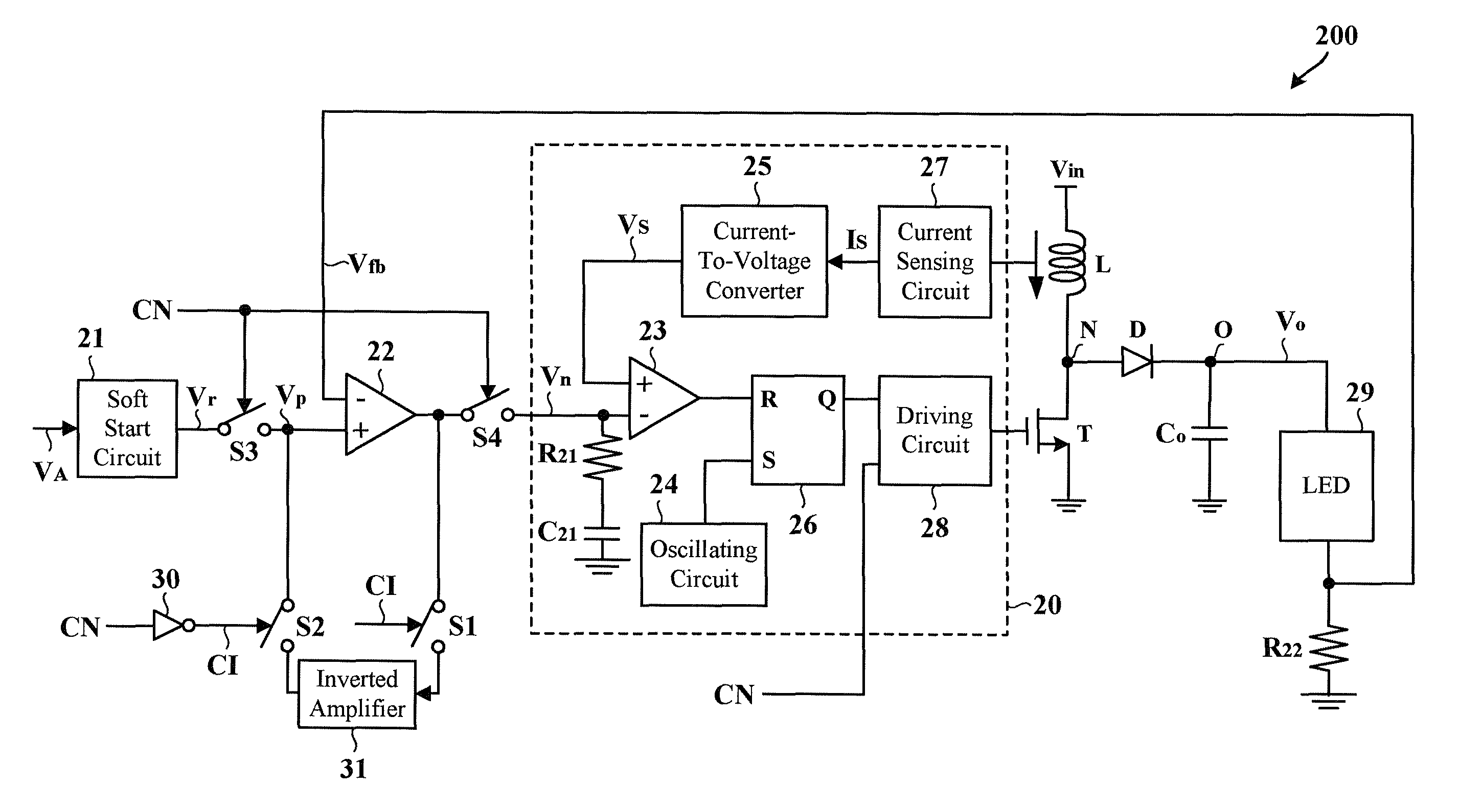
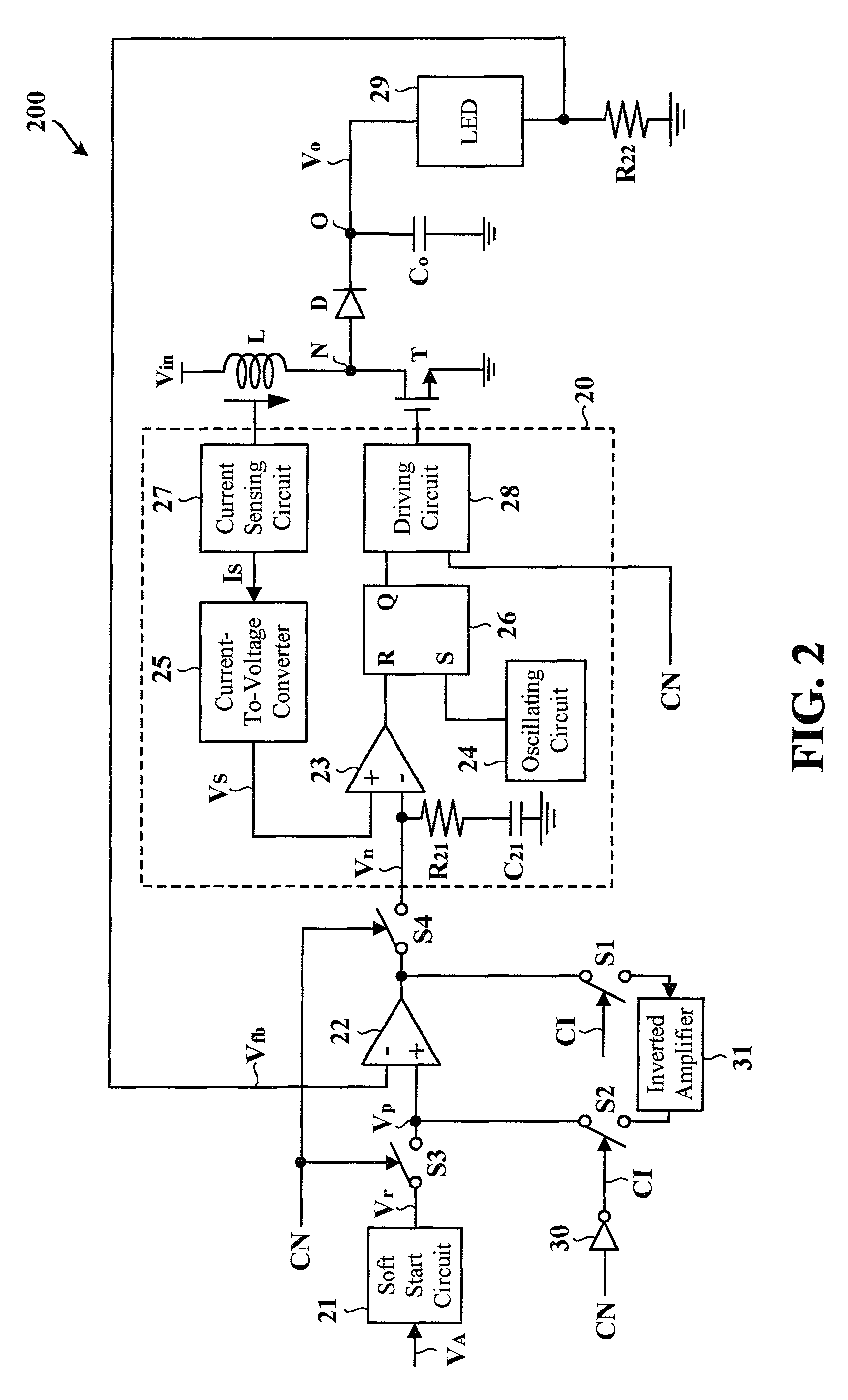
[0011]FIG. 2 is a circuit diagram showing a LED dimming control circuit 200 according to the present invention. In the example shown in FIG. 2, the LED dimming control circuit 200 is implemented by a boost-type voltage converter which converts an input voltage Vin into an output voltage Vo, so as to drive a LED 29. The LED dimming control circuit 200 comprises a soft start circuit 21, an error amplifier 22, switches S1 to S4, an inverter 30, an inverted amplifier 31, a switching control circuit 20, an inductor L, a transistor T, a diode D, a resistor R22, and an output capacitor Co. The inductor L, the transistor T, and the diode D are commonly coupled to a node N. The anode terminal of the LED 29, the diode D, and the output capacitor Co are commonly coupled to a node O. The connection point of the resistor R22 and the cathode terminal of the LED 29 is used to p...


PUM


Abstract

A LED dimming control circuit that avoids a higher output voltage than expected is provided. The LED dimming control circuit comprises an inductor, a transistor, a dimming control signal, a feedback signal, a switching control circuit, an error amplifier, and an inverted amplifier. The inductor and the transistor are coupled to a node. The switching control circuit is controlled by the dimming control signal and the feedback signal. The transistor is controlled by the switching control circuit. The output terminal of the error amplifier and the non-inverted input terminal of the error amplifier form a negative feedback path via the inverted amplifier.

Description

BACKGROUND OF THE INVENTION[0001]1. Field of the Invention[0002]The present invention relates to a dimming control circuit. More particularly, the present invention relates to a LED dimming control circuit.[0003]2. Description of the Related Art[0004]FIG. 1 is a circuit diagram showing a conventional LED dimming control circuit 100. In the example shown in FIG. 1, the LED dimming control circuit 100 is implemented by a boost-type voltage converter which converts an input voltage Vin1 into an output voltage Vo1, so as to drive a LED 19. A switching control circuit 10 comprises a capacitor C11, a resistor R11, a comparator 13, an oscillating circuit 14, a current-to-voltage converter 15, a latch 16, a current sensing circuit 17, and a driving circuit 18. The connection point of the resistor R12 and the cathode terminal of the LED 19 is used to provide a feedback signal Vfb1. The switching control circuit 10 is used to control the transistor T1 in response to a dimming control signal C...

Claims


Application Information

Patent Timeline
Patent Type & Authority Patents(United States)
IPC IPC(8): G05F1/00
CPCH05B33/0848H05B33/0851Y10S315/04H05B45/14H05B45/10
Inventor CHANG CHIEN, SHANG-YUCHEN, TIEN-TZU
Owner GLOBAL MIXED MODE TECH
Why Eureka
Try Eureka