Pixel configuration structure and organic light-emitting display panel with pixel configuration structure
A pixel arrangement and sub-pixel technology, applied in electrical components, electrical solid-state devices, circuits, etc., can solve problems such as complex driving and poor picture quality, achieve the effect of improving display brightness, avoiding cost increases, and improving use effects
- Summary
- Abstract
- Description
- Claims
- Application Information
AI Technical Summary
Problems solved by technology
Method used
Image
Examples
Embodiment 1
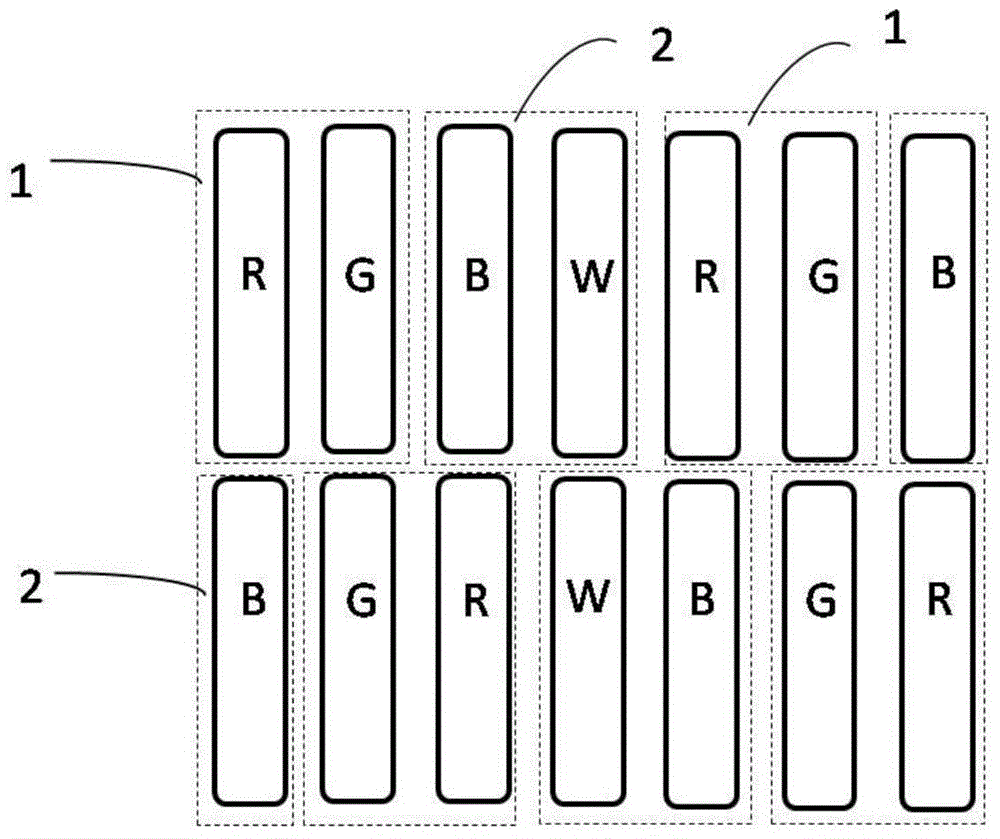
[0030] This embodiment provides a pixel arrangement structure, such as figure 2 As shown, it includes 2 rows and 2 columns of first pixel units 1, and a second pixel unit 2 is arranged between each row adjacent to the first pixel unit 1; the first pixel unit 1 includes the same plane A red sub-pixel R and a green sub-pixel G, the second pixel unit 2 includes a white sub-pixel W and a blue sub-pixel B. Two adjacent first pixel units 1 share the second pixel unit 2 between them.
[0031] Both the white sub-pixel W and the blue sub-pixel B are strip-shaped, and their length direction is perpendicular to the row direction; the red sub-pixel R and the green sub-pixel G are both strip-shaped, and their length direction is perpendicular to the row direction. The row direction is vertical and arranged side by side along the row direction.
[0032] Along the column direction, the pixel arrangement structures of two adjacent rows are mirror images of each other.
[0033] In this emb...
Embodiment 2
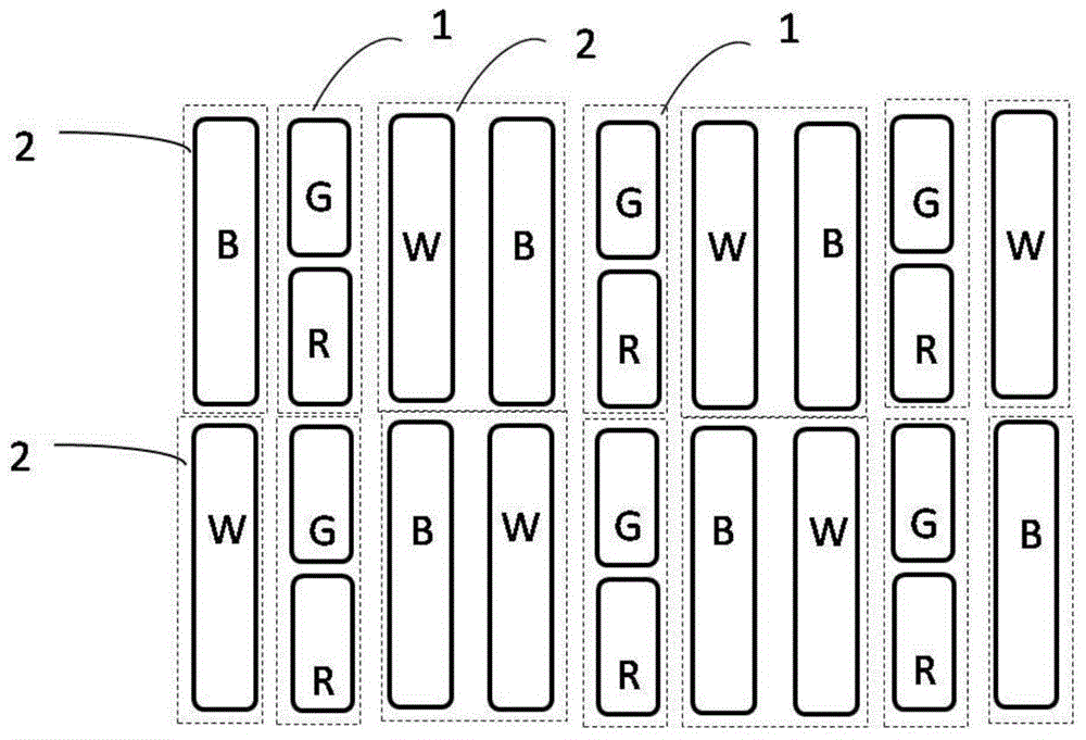
[0036] This embodiment provides a pixel arrangement structure, such as image 3 As shown, it includes 2 rows and 3 columns of first pixel units 1, and a second pixel unit 2 is arranged between each row adjacent to the first pixel unit 1; the first pixel unit 1 includes the same plane A red sub-pixel R and a green sub-pixel G, the second pixel unit 2 includes a white sub-pixel W and / or a blue sub-pixel B. Moreover, at least one of the second pixel units 2 includes the white sub-pixel W, and two adjacent second pixel units 2 are not all white sub-pixels W. Two adjacent first pixel units 1 share the second pixel unit 2 between them.
[0037] As a variable embodiment of the present invention, the first pixel unit 1 can also have m rows and n columns, m is a non-zero natural number, and n is a natural number not less than 2, both of which can achieve the purpose of the present invention and belong to the scope of the present invention protected range.
[0038] Both the white sub...
Embodiment 3
[0043] This embodiment provides a pixel arrangement structure, such as Figure 4 As shown, it includes 1 row and 4 columns of first pixel units 1, and a second pixel unit 2 is arranged between each row adjacent to the first pixel unit 1; the first pixel unit 1 includes coplanar Red sub-pixel R and green sub-pixel G, the second pixel unit 2 includes white sub-pixel W and / or blue sub-pixel B; at least one second pixel unit 2 includes the white sub-pixel W, adjacent The two second pixel units 2 are not all white sub-pixels W. Two adjacent first pixel units 1 share the second pixel unit 2 between them.
[0044] Both the white sub-pixel W and the blue sub-pixel B are strip-shaped, and their length direction is perpendicular to the row direction; the red sub-pixel R and the green sub-pixel G are arranged side by side along the column direction, and both of them are in the column direction. The sum of the lengths in the direction is smaller than the length of the white sub-pixel or...
PUM
 Abstract
Description
Claims
Application Information
 - R&D
- Intellectual Property
- Life Sciences
- Materials
- Tech Scout
- Unparalleled Data Quality
- Higher Quality Content
- 60% Fewer Hallucinations
Browse by: Latest US Patents, China's latest patents, Technical Efficacy Thesaurus, Application Domain, Technology Topic, Popular Technical Reports.
© 2025 PatSnap. All rights reserved.Legal|Privacy policy|Modern Slavery Act Transparency Statement|Sitemap|About US| Contact US: help@patsnap.com


