Service provider boundary routers, system and method for achieving fast VPN rerouting

A service provider boundary and router technology, applied in the field of data communication, can solve the problems of user service interruption, unable to solve the single point of failure of dual-homed/multi-homed PE equipment, remote PE equipment unable to support VPNFRR, etc., to achieve fast switching. Effect

Inactive Publication Date: 2015-03-25
MAIPU COMM TECH CO LTD
View PDF3 Cites 9 Cited by
  • Summary
  • Abstract
  • Description
  • Claims
  • Application Information

AI Technical Summary

Problems solved by technology

[0005] In MPLS L3VPN CE dual-homing/multi-homing PE scenarios, two/multiple homed PE devices are required to configure the same RD (Route Distinguisher routing identifier) ​​for the same VRF (VPN Routing Forwarding VPN routing forwarding), and the VRF router identifier includes The following three formats: when the type value is 0, the Administrator subfield occupies 2 bytes, and the Assigned number subfield occupies 4 bytes. The format is: 16-bit autonomous system number: 32 user-defined numbers; when its type When the value is 1, the Administrator subfield occupies 4 bytes, and the Assigned number subfield occupies 2 bytes. The format is: 32-bit IPv4 address: 16 user-defined numbers; when the type value is 2, the Administrator subfield occupies 2 bytes, the assigned number subfield occupies 4 bytes, its format is: 32-bit autonomous system number: 16 user-defined numbers, using the existing VPN FRR technology: the remote PE device selects a qualified VPNv4 route according to the matching policy , the preferred route and the second-b...

Method used


Image

  • Service provider boundary routers, system and method for achieving fast VPN rerouting
  • Service provider boundary routers, system and method for achieving fast VPN rerouting
  • Service provider boundary routers, system and method for achieving fast VPN rerouting

Examples


Embodiment

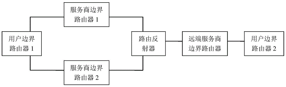
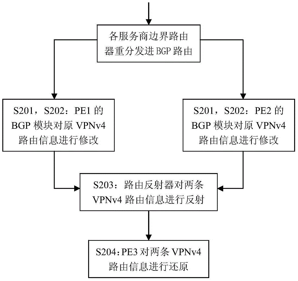
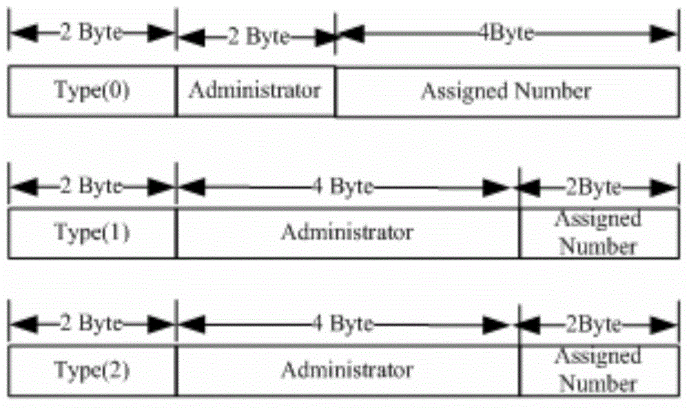
[0037] The embodiment of the present invention adopts two kinds of service provider border routers, the first one is: service provider border router, including a router identification preset module, a sending module, a dynamic identification generation module and a router identification replacement module, wherein the router identification preset module It is used to configure the VRF router ID; the dynamic ID generation module, when the private network route is redistributed into the BGP route, uses the PPP protocol magic word to dynamically generate a new VRF router ID for the service provider border router; the router ID replacement module, through the MP - When the IBGP protocol publishes the VPNv4 route to the route reflector, replace the original VRF router identifier in the VPNv4 routing information with the new VRF router identifier, specifically: replace the original VRF router identifier in the MP-NLRI attribute with the new VRF router identifier, And add the original...


PUM


Abstract

The invention relates to a data communication technology, solves the problem that an existing VPN FRR technology cannot be implemented under the condition that a route reflector exists between a dual-homing/multi-homing PE and a far-end PE and provides service provider boundary routers, system and method for achieving fast VPN rerouting. According to the technical scheme, two novel service provider boundary routers are provided, the first service provider boundary router comprises a router identification presetting module, a sending module, a dynamic identification generating module and a router identification replacing module, and the second service provider boundary router comprises a receiving module and an analysis recovery module. The service provider boundary routers, system and method for achieving the fast VPN rerouting has the advantages that the far-end service provider boundary router can still support the fast VPN rerouting under the condition that the route reflector exists between the dual-homing/multi-homing service provider boundary router and the far-end service provider boundary router and is suitable for dual-homing/multi-homing networking.

Description

technical field [0001] The invention relates to data communication technology, in particular to VPN fast rerouting technology. Background technique [0002] L3VPN adopts MPLS (Multiprotocol Label Switching) technology to build an IP private network on the backbone network to realize cross-regional, high-speed and reliable forwarding of private data packets. Using MPLS VPN (Virtual Private Network virtual private network) technology can convert existing An IP network is decomposed into logically isolated networks. The application of this logically isolated network can be varied: it can be used to solve the interconnection of enterprises, the interconnection of the same / different departments of the government, and it can also be used to provide new services, such as opening a dedicated VPN for IP telephony services. [0003] As users have higher and higher requirements for network reliability, the single point of failure of network service provider equipment has become a bott...

Claims


Application Information

Patent Timeline
IPC IPC(8): H04L12/713H04L12/46H04L45/586
Inventor 岳刚
Owner MAIPU COMM TECH CO LTD
Why Eureka
Try Eureka