
Multifunctional router device with support

A router and multi-functional technology, applied in the direction of digital transmission system, electrical components, transmission system, etc., can solve the problems of inconvenience, reducing the service life of the router, damage, etc., and achieve the effect of ensuring the network connection, prolonging the service life and avoiding the loss of the network cable

Inactive Publication Date: 2015-03-25
XIAN HIGH TECH IND DEV ZONE WEST INFORMATION HARBOR
View PDF0 Cites 0 Cited by
  • Summary
  • Abstract
  • Description
  • Claims
  • Application Information

AI Technical Summary

Problems solved by technology

[0002] With the popularity of the Internet, the demand for routers has increased significantly. However, the current routers are placed flat on the table, and the bottom cannot dissipate heat. At the same time, they are placed in any position, and have no fixed relationship with the placement. When they are accidentally bumped into the router, it will move. The bottom cannot dissipate heat, resulting in network disconnection, which brings great inconvenience to people's study and work. Collision may also cause falling and damage, which reduces the service life of the router. The router occupies a certain space, leaving no place for other ornaments.

Method used


Image

  • Multifunctional router device with support
  • Multifunctional router device with support

Examples


Embodiment 1

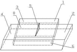
[0018] The invention provides a multifunctional router device with a bracket, such as figure 1 As shown, the router housing 1 is included, and the router housing 1 is vertically plugged into the bracket 2. The upper surface of the router housing 1 is provided with a photo frame 3, and the lower surface and surroundings of the router housing 1 are distributed with cooling holes.

[0019] Since the fixed router is vertically plugged into the bracket 2, it can prevent movement, avoid network cables falling off, and ensure network connectivity; prevent the router from colliding, falling, and being damaged, thereby protecting the router and prolonging its service life.

[0020] After the router is plugged in vertically, the lower surface that was originally close to the desktop can be released vertically as a cooling hole, so the upper surface where the cooling holes were previously distributed can be made into a closed structure as a photo frame.

Embodiment 2

[0022] The support 2 in Embodiment 1 is composed of a plane support 4 that can be placed on the table and a facade support 5 that can stand on the desktop. The facade support 5 is arranged obliquely, and the bottom of the facade support 5 is fixed to the side of the plane support 4 connection, there is a groove 6 on the plane bracket 4, one end of the router housing 1 is placed in the groove 6, the groove 6 matches the structure of one side of the router housing 1, and the router housing 1 is inserted into the In groove 6.

[0023] The upper surface of the router housing 1 is a plane, the upper surface of the router housing 1 is fixed to three sides of the rectangular photo frame 3, the remaining side is an opening, the photo frame 3 is a plastic film 8, and the photo passes through the opening side of the photo frame 3 It is inserted between the plastic film 8 and the upper surface of the router housing 1 .

Embodiment 3

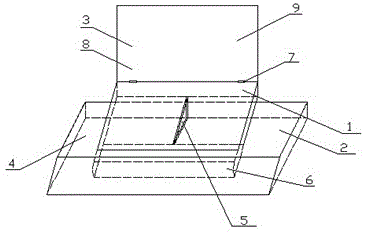
[0025] Such as figure 2 As shown, the upper edge of the upper surface of the router housing 1 in Embodiment 1 is rotationally connected with the lower edge of the photo frame 3 through the rotating shaft 7. The photo frame 3 is a rectangular plastic plate 9, and the upper surface of the router housing 1 is distributed with cooling holes. The plastic plate 9 when covering the upper surface of the router housing 1, the inner side of the plastic plate 9 is fixed to the three sides of the rectangular plastic film 8.

[0026] In this embodiment, the photo frame 3 is designed to be a reversible structure. When used as a photo frame, the photo frame 3 can be turned to the top. Since the photo frame 3 is turned to the top, part of the space on the upper surface of the router housing 1 can be liberated, so Heat dissipation holes are added on the upper surface of the router housing 1 to dissipate heat. The fixed router prevents the network cable from falling off and ensures the networ...


PUM


Abstract

The invention belongs to the technical field of network equipment and particularly relates to a multifunctional router device with a support. The multifunctional router device comprises a shell, the movable support for fixing the shell and a photo frame arranged on the shell. The shell is fixed to a groove, a support body where the groove is formed and a support body erected on a desktop are connected, the router is fixed to the support, the periphery of the router can dissipate heat, and the router can be prevented from swinging randomly and moving randomly. The photo frame is arranged on the surface of the shell and can contain a photo or other cards, practicability is achieved, and the decoration function is achieved. The multifunctional router device with the support solves the problems that at present, a router is horizontally placed, the bottom of the router cannot dissipate heat, circuits disengage when the router is placed and moved at will, and the network stability is poor; the trouble that connection is prone to being broken when people surf the Internet is saved, the problem that the router is damaged due to colliding and falling is solved, and the service life of the router is prolonged; meanwhile, the position for the placement of a photo clip is omitted, the function of the router is expanded, the limited space of the desktop is saved, and the router is practical and attractive.

Description

technical field [0001] The invention relates to the field of computer network equipment, in particular to a multifunctional router with a movable support. Background technique [0002] With the popularity of the Internet, the demand for routers has increased significantly. However, the current routers are placed flat on the table, and the bottom cannot dissipate heat. At the same time, they are placed in any position, and have no fixed relationship with the placement. When they are accidentally bumped into the router, it will move. The bottom cannot dissipate heat, resulting in network disconnection, which brings great inconvenience to people's study and work. Collision may also cause falling and damage, which reduces the service life of the router. The router occupies a certain space, leaving no place for other ornaments. . Contents of the invention [0003] The purpose of the present invention is to solve the problem that the current router is placed flat on the table w...

Claims


Application Information

Patent Timeline
IPC IPC(8): H04L12/771H04L45/60
Inventor 杨兴
Owner XIAN HIGH TECH IND DEV ZONE WEST INFORMATION HARBOR
Learn More