
Buck-boost circuit for electromagnetic heating device and its control method

A technology of electromagnetic heating device and buck-boost circuit, which is applied in the direction of induction heating control, induction heating, output power conversion device, etc., can solve the problems of IGBT temperature rise, power increase difficulty, high turn-on voltage, etc., to achieve power increase, The control method is simple and reliable, and the effect of reducing the opening voltage

Inactive Publication Date: 2016-05-11
MIDEA GRP CO LTD +1
View PDF6 Cites 0 Cited by
  • Summary
  • Abstract
  • Description
  • Claims
  • Application Information

AI Technical Summary

Problems solved by technology

[0002] In the prior art, single-tube parallel resonant circuits are used in electromagnetic heating devices such as induction cookers. However, when the electromagnetic heating device has high voltage and low power, the turn-on voltage of IGBT (Insulated Gate Bipolar Transistor, insulated gate bipolar transistor) is high and the turn-on loss is large. , IGBT temperature rises and is easy to be damaged; when the electromagnetic heating device is at low voltage and high power, it is difficult to increase the power, so there is a need for improvement

Method used


Image

  • Buck-boost circuit for electromagnetic heating device and its control method
  • Buck-boost circuit for electromagnetic heating device and its control method
  • Buck-boost circuit for electromagnetic heating device and its control method

Examples


Embodiment Construction

[0028] The embodiments of the present invention are described in detail below. Examples of the embodiments are shown in the accompanying drawings, in which the same or similar reference numerals indicate the same or similar elements or elements with the same or similar functions. The embodiments described below with reference to the accompanying drawings are exemplary, and are only used to explain the present invention, and cannot be construed as limiting the present invention.

[0029] The following disclosure provides many different embodiments or examples for implementing different structures of the present invention. In order to simplify the disclosure of the present invention, the components and settings of specific examples are described below. Of course, they are only examples, and are not intended to limit the invention. In addition, the present invention may repeat reference numbers and / or letters in different examples. This repetition is for the purpose of simplificat...


PUM


Abstract

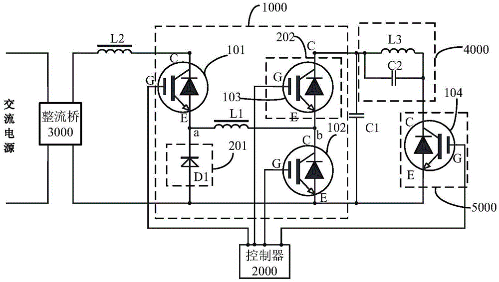
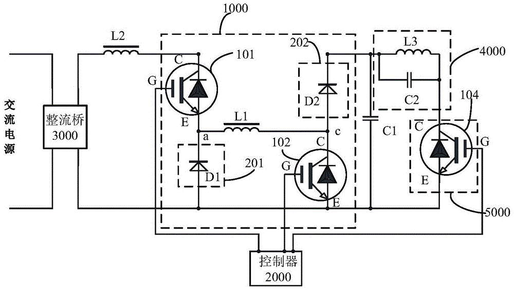
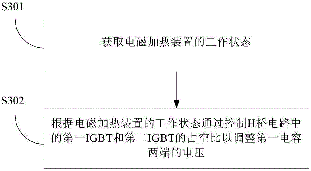
The invention discloses a buck-boost circuit for an electromagnetic heating device and a control method thereof. The buck-boost circuit comprises an H-bridge circuit, a first capacitor, a resonance circuit and a controller, wherein the H-bridge circuit comprises a first IGBT, a first switch tube, a second IGBT, a second switch tube and a first inductor, the input end of the H-bridge circuit is connected with the output end of a rectifier bridge in the electromagnetic heating device, the first capacitor is connected to the output end of the H-bridge circuit in parallel, the resonance circuit is connected with the first capacitor, the controller is connected with the G pole of the first IGBT and the G pole of the second IGBT, and the voltage across the two ends of the first capacitor is adjusted according to the working state of the electromagnetic heating device by controlling the duty ratio of the first IGBT and the duty ratio of the second IGBT. According to the buck-boost circuit, the voltage of the capacitor is adjusted by controlling the duty ratio of each IGBT, so that the voltage of the resonance circuit is increased or reduced, and then the turn-on loss of a switching device is reduced when the electromagnetic heating device is in the high-voltage and low-power state and power is increased quickly when the electromagnetic heating device is in the low-voltage and high-power state.

Description

Technical field [0001] The invention relates to the field of household appliances, in particular to a buck-boost circuit used in an electromagnetic heating device and a control method thereof. Background technique [0002] In the prior art, a single-tube parallel resonant circuit is used in an electromagnetic heating device such as an induction cooker. However, when the electromagnetic heating device is at high voltage and low power, the IGBT (Insulated Gate Bipolar Transistor, insulated gate bipolar transistor) has high turn-on voltage and large turn-on loss. IGBT temperature rises and is easy to damage; when the electromagnetic heating device has low voltage and high power, it is difficult to increase the power, so there is a need for improvement. Summary of the invention [0003] The purpose of the present invention is to solve one of the above technical defects at least to a certain extent. [0004] To this end, an object of the present invention is to provide a buck-boost circ...

Claims


Application Information

Patent Timeline
Patent Type & Authority Patents(China)
IPC IPC(8): H05B6/06H02M7/219
Inventor 汪钊
Owner MIDEA GRP CO LTD
Learn More