Contactless electrical power supply device

A non-contact power supply and non-contact technology, applied in circuit devices, electrical components, electrical components, etc., can solve the problems of increased load weight, disconnection, etc., and achieve the effect of easy frequency adjustment and elimination of the increase in load weight.

Active Publication Date: 2015-03-25
FUJI KK
View PDF6 Cites 3 Cited by
  • Summary
  • Abstract
  • Description
  • Claims
  • Application Information

AI Technical Summary

Problems solved by technology

However, cables for power supply have disadvantages such as an increase in load weight and a risk of disconnection due to metal fatigue.

Method used


Image

  • Contactless electrical power supply device
  • Contactless electrical power supply device
  • Contactless electrical power supply device

Examples


Embodiment Construction

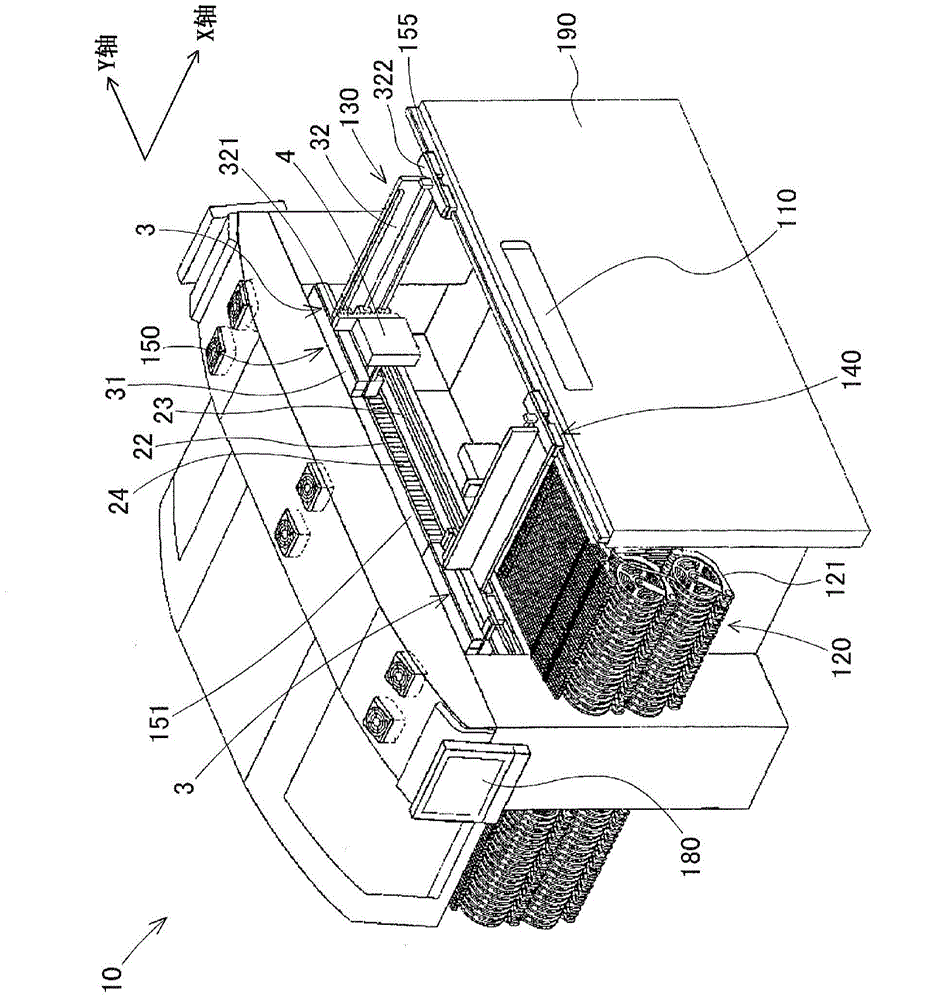
[0037] First, the component mounting machine 10 to which the present invention can be applied will be described. figure 1 It is a perspective view showing the overall configuration of a component mounting machine 10 to which the contactless power supply device 1 according to the first embodiment of the present invention can be applied. The component mounting machine 10 is a device for mounting a plurality of components on a board, and is configured by arranging two sets of component mounting units of the same configuration substantially symmetrically. Here, to figure 1 The component mounting unit in the state where the cover on the right near front side is removed will be described as an example. It should be noted that the width direction of the component mounting machine 10 from the left rear side to the right near side in the figure is the X-axis direction of loading and unloading substrates, and the component mounting machine 10 from the left near front side to the right ...


PUM


Abstract

This contactless electrical power supply device (1) is provided with: a securing part (2); a first moveable part (Y-axis moving element (3)) that is moveably mounted on the securing part (2); a second moveable part (component mounting head (4)) that is mounted so as to be capable of moving relative to the first moveable part (3); a first contactless electrical power supply mechanism (high-frequency electrical power source circuit (51), first electrical power supply electrode plates (52, 53), first electrical power receiving electrode plates (55, 56), first electrical power receiving circuit (57)) for supplying electrical power in a contactless manner from the securing part (2) to a first electrical load (L1) on the first moveable part (3); and a second contactless electrical power supply mechanism ((51, 52, 53, 55, 56, 57), high-frequency electrical power transmitting circuit (61), second electrical power supply electrode plates (62, 63), second electrical power receiving electrode plates (65, 66), second electrical power receiving circuit (67)) for supplying electrical power in a contactless manner from the securing part (2) via the first moveable part (3) to a second electrical load (L2) on the second moveable part (4). Consequently, contactless electrical power supply is carried out from the securing part (2) to the second electrical load (L2) on the second moveable part (4) for driving, in combination, a plurality of drive mechanisms (linear motor device (150), ball screw feed mechanism).

Description

technical field [0001] The present invention relates to a non-contact power supply device that supplies power from a fixed part to an electrical load on a moving part in a non-contact manner. Contactless power supply for mobile equipment. Background technique [0002] There are solder printing machines, component mounting machines, reflow soldering machines, board inspection machines, etc. as board working equipment for manufacturing boards on which many components are mounted, and board production lines are often constructed by connecting them with a board transfer device. Most of these substrate working equipment include: a moving unit that moves above the substrate to perform a predetermined operation; and two sets of drive mechanisms that drive the moving unit in two orthogonal axial directions. As a drive mechanism, a linear motor device or a ball screw feed mechanism is often used. The linear motor device includes: a track member in which a plurality of magnets are a...

Claims


Application Information

Patent Timeline
IPC IPC(8): H05K13/04H02J17/00
CPCH05K13/0406H02J50/50H02J50/05
Inventor 神藤高广野村壮志石浦直道泷川慎二
Owner FUJI KK
Why Eureka
Try Eureka