A multi-point pressurized liquid die forging method
A liquid die forging and multi-point technology, which is applied in the field of liquid die forging and metal material liquid die forging, can solve the problems of inability to realize multi-point pressurization and difficulty in producing complex workpieces, and achieve stable and reliable workpiece quality, uniform structure and performance Good performance and reduced tonnage
- Summary
- Abstract
- Description
- Claims
- Application Information
AI Technical Summary
Problems solved by technology
Method used
Image
Examples
Embodiment 1
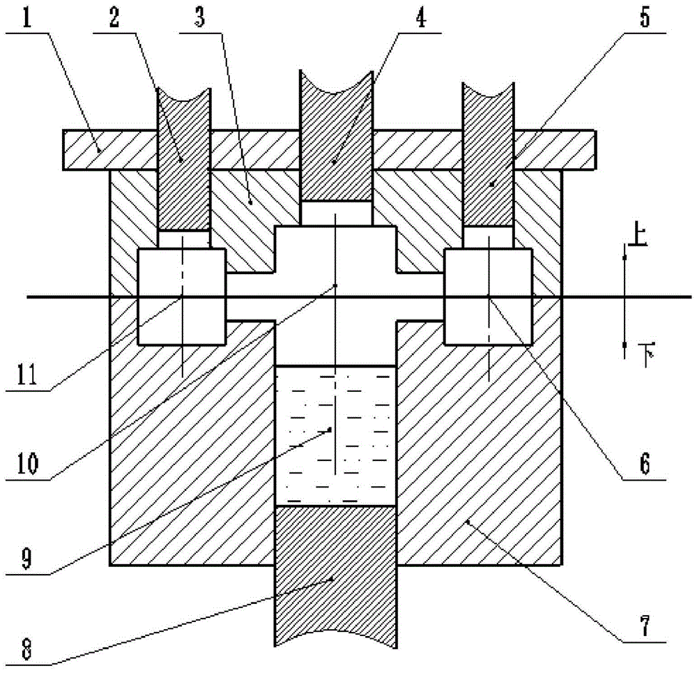
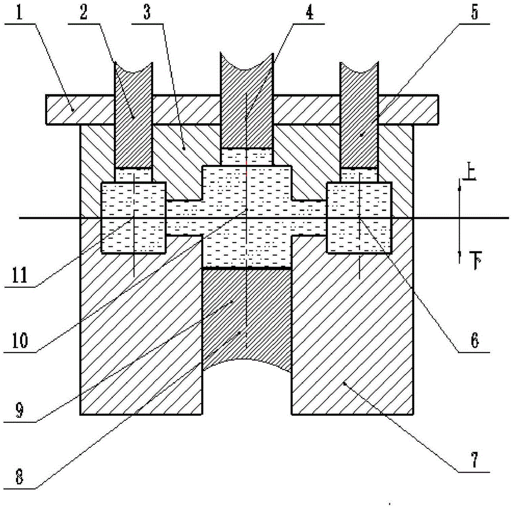
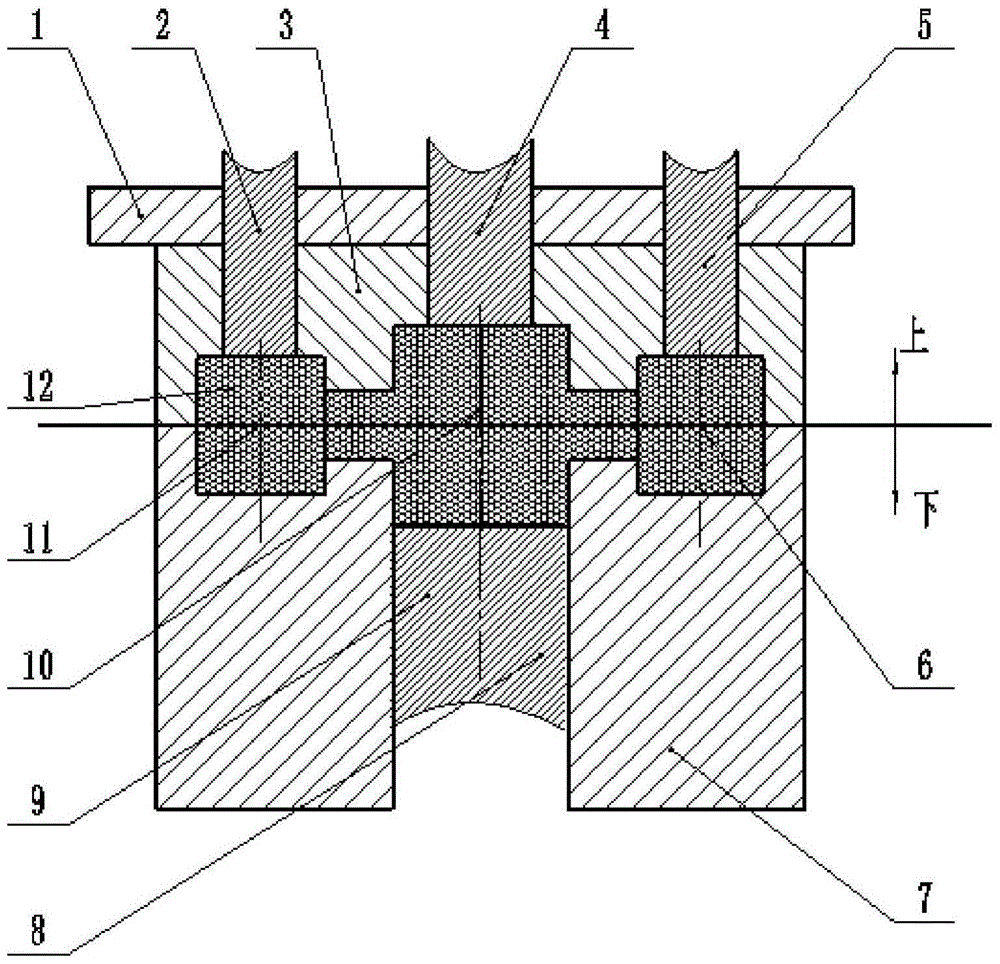
[0041] The workpiece of the embodiment of the present invention has three hot joint positions, and the mold for liquid die forging (referred to as liquid forging) of the workpiece at least includes a clamping indenter, a feeding indenter, an upper die, a lower die, a mold cavity, a lower press Head, pressure chamber. This implementation provides a 4-point pressurized liquid die forging method suitable for this workpiece, including the following five key steps, combined with Figure 1 to Figure 3 The mold clamping diagram of each stage in the liquid forging process shown is as follows:
[0042](1) Adjust the position and stroke of the feeding head: adjust the position and stroke of the first feeding head 2, the second feeding head 4, and the third feeding head 5, so that the first hot joint position 11, The second thermal joint position 10 and the third thermal joint position 6 each have a corresponding feeding head. The stroke of each feeding head is twice the compact compres...
Embodiment 2
[0049] The workpiece of the embodiment of the present invention is a frame-like part with 6 hot joint positions, and the mold for liquid forging the workpiece includes at least a clamping ram, a feeding ram, an upper die, a lower die, a die cavity, and a lower die. Head, pressure chamber. This implementation provides a 7-point pressurized liquid die forging method suitable for this workpiece, including the following five key steps, described as follows:
[0050] (1) Adjust the position and stroke of the feeding head: adjust the position and stroke of the 6 feeding heads, so that each hot spot has a corresponding feeding head, and each feeding head The stroke is 6 times the compact compression amount of each hot joint position, and the pressure end surface area of each feeding pressure head is equal to 0.75 times the cross-sectional area of the corresponding hot joint position;
[0051] (2) Pouring: The alloy liquid whose temperature is higher than the liquidus temperature...
Embodiment 3
[0058] The workpiece in the embodiment of the present invention is a rod part with 7 hot joint positions. The mold for liquid forging the workpiece includes at least a clamping ram, a feeding ram, an upper die, a lower die, a mold cavity, a lower press Head, pressure chamber. This implementation provides an 8-point pressurized liquid die forging method suitable for this workpiece, including the following five key steps, described as follows:
[0059] (1) Adjust the position and stroke of the feeding head: adjust the position and stroke of the 7 feeding heads so that each hot spot has a corresponding feeding head. The stroke is 10 times the compact compression amount of each hot joint position, and the pressure end surface area of each feeding pressure head is equal to 1 time the cross-sectional area of the corresponding hot joint position;
[0060] (2) Pouring: The alloy liquid whose temperature is 100°C higher than the liquidus temperature of the liquid forging alloy is ...
PUM
 Abstract
Description
Claims
Application Information
 - R&D
- Intellectual Property
- Life Sciences
- Materials
- Tech Scout
- Unparalleled Data Quality
- Higher Quality Content
- 60% Fewer Hallucinations
Browse by: Latest US Patents, China's latest patents, Technical Efficacy Thesaurus, Application Domain, Technology Topic, Popular Technical Reports.
© 2025 PatSnap. All rights reserved.Legal|Privacy policy|Modern Slavery Act Transparency Statement|Sitemap|About US| Contact US: help@patsnap.com


