a clamping mechanism

A clamping mechanism and flange technology, applied in auxiliary devices, auxiliary welding equipment, welding/cutting auxiliary equipment, etc., can solve the problems of difficult clamping of parts, low work efficiency, low practicability, etc., and achieve compact compression parts. , Simple structure, fast operation effect

Active Publication Date: 2017-01-04
TIANJIN CATARC AUTO HI TECH
View PDF10 Cites 2 Cited by
  • Summary
  • Abstract
  • Description
  • Claims
  • Application Information

AI Technical Summary

Problems solved by technology

[0002] In the existing technology, it is often necessary to clamp the workpiece, but there are problems in the clamping mechanism: the positioning and clamping of the inner and outer sides of the flange cannot be completed at the same time, and the practicability is small; the structure is complex, the parts are difficult to clamp, and the adjustment is time-consuming and laborious , low work efficiency

Method used


Image

  • a clamping mechanism
  • a clamping mechanism
  • a clamping mechanism

Examples


Embodiment Construction

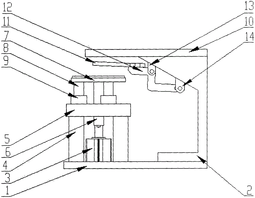
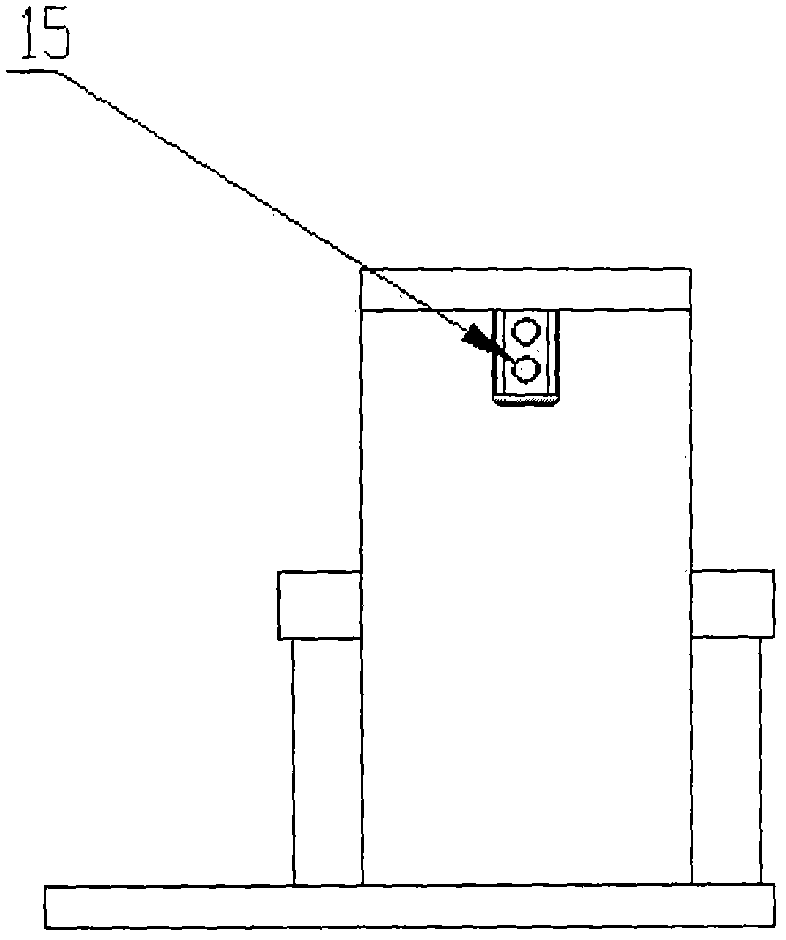
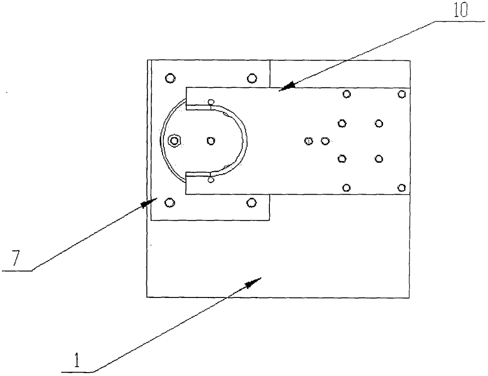
[0017] Such as Figure 1-3 as shown,

[0018] The technical solution of the present invention is: a clamping mechanism, including a base plate 1 and a flange support seat 2 arranged at the right end of the base plate 1, the upper left end of the base plate 1 is provided with a first cylinder 3, a support column 4, two support The upper end of the column 4 is connected through the support plate 5, the first cylinder 3 is arranged between the two support plates 5, the piston rod of the first cylinder 3 is connected with the cone support plate 7 through the push rod 6, and the push rod 6 passes through On the support plate 5, the cone support plate 7 is used to place the cone, and the two ends of the lower side of the cone support plate 7 are respectively connected with two guide posts 8, and the cone support plate 7 is matched with the bearing 9 through the guide post 8, and the bearing 9 is in the On the support plate 5, the first cylinder 3 on the base plate 1 pushes the push...


PUM


Abstract

The invention provides a clamping mechanism which comprises a bottom plate, a first cylinder, two support columns and a flange support seat. The first cylinder, the support columns and the flange support seat are arranged on the bottom plate, the upper ends of the two support columns are connected with each other by support plates, the first cylinder is arranged between the two support plates, a piston rod of the first cylinder is connected with a cone support plate by a push rod, the push rod penetrates the upper surfaces of the support plates, two ends of the lower side of the cone support plate are respectively connected with two guide columns, the cone support plate is matched with bearings via the guide columns, the bearings are arranged on the support plates, the upper end of the flange support seat is perpendicularly connected with one end of a flange positioning plate, the other end of the flange positioning plate is arc-shaped, a flange pressure plate is connected with a connecting frame fixing piece and a cylinder connecting piece by a connecting frame, and the cylinder connecting piece is connected with a second cylinder. The clamping mechanism has the advantages that the clamping mechanism is provided with a flange compressing mechanism which is pushed by the cylinders, so that positioning and compressing actions can be synchronously carried out on the inner surface and the outer surface of a flange by the flange positioning plate and the flange pressure plate at one step; the push rod can be pushed by the cylinders, and the cone support plate can be lifted, so that a cone can be assuredly perpendicularly positioned at one step.

Description

technical field [0001] The invention belongs to the field of welding clamping tooling, and in particular relates to a clamping mechanism. Background technique [0002] In the existing technology, it is often necessary to clamp the workpiece, but there are problems in the clamping mechanism: the positioning and clamping of the inner and outer sides of the flange cannot be completed at the same time, and the practicability is small; the structure is complex, the parts are difficult to clamp, and the adjustment is time-consuming and laborious , low work efficiency. Contents of the invention [0003] The purpose of the present invention is to provide a clamping mechanism which is simple in structure, can be operated quickly and can simultaneously complete the positioning and clamping of the inner and outer sides of the flange, and is especially suitable for mass production clamping. [0004] The technical solution of the present invention is: a clamping mechanism, including a...

Claims


Application Information

Patent Timeline
Patent Type & Authority Patents(China)
IPC IPC(8): B23K37/04
CPCB23K37/0435
Inventor 王庆武李善亭葛岩董晓菲李兆燕
Owner TIANJIN CATARC AUTO HI TECH
Why Eureka
Try Eureka