
Rotary electrode electric-fusion welding automatic back gouging device

A rotating electrode, automatic cleaning technology, applied in arc welding equipment, welding equipment, manufacturing tools, etc., to achieve the effect of easy operation, good root cleaning surface quality, and root cleaning quality assurance

Inactive Publication Date: 2010-07-28
CHINA PETROLEUM PIPELINE BUREAU
View PDF1 Cites 0 Cited by
  • Summary
  • Abstract
  • Description
  • Claims
  • Application Information

AI Technical Summary

Problems solved by technology

The design idea of ​​the present invention is to use a disc-type rotating electrode to cause an arc between the disc-type rotating electrode and the weld seam of the workpiece, and to use compressed air and the grinding effect of the electrode disc to automatically clean the root of the melted weld seam to solve the existing problem. Insufficient cleaning technology

Method used


Image

  • Rotary electrode electric-fusion welding automatic back gouging device
  • Rotary electrode electric-fusion welding automatic back gouging device
  • Rotary electrode electric-fusion welding automatic back gouging device

Examples


Embodiment 1

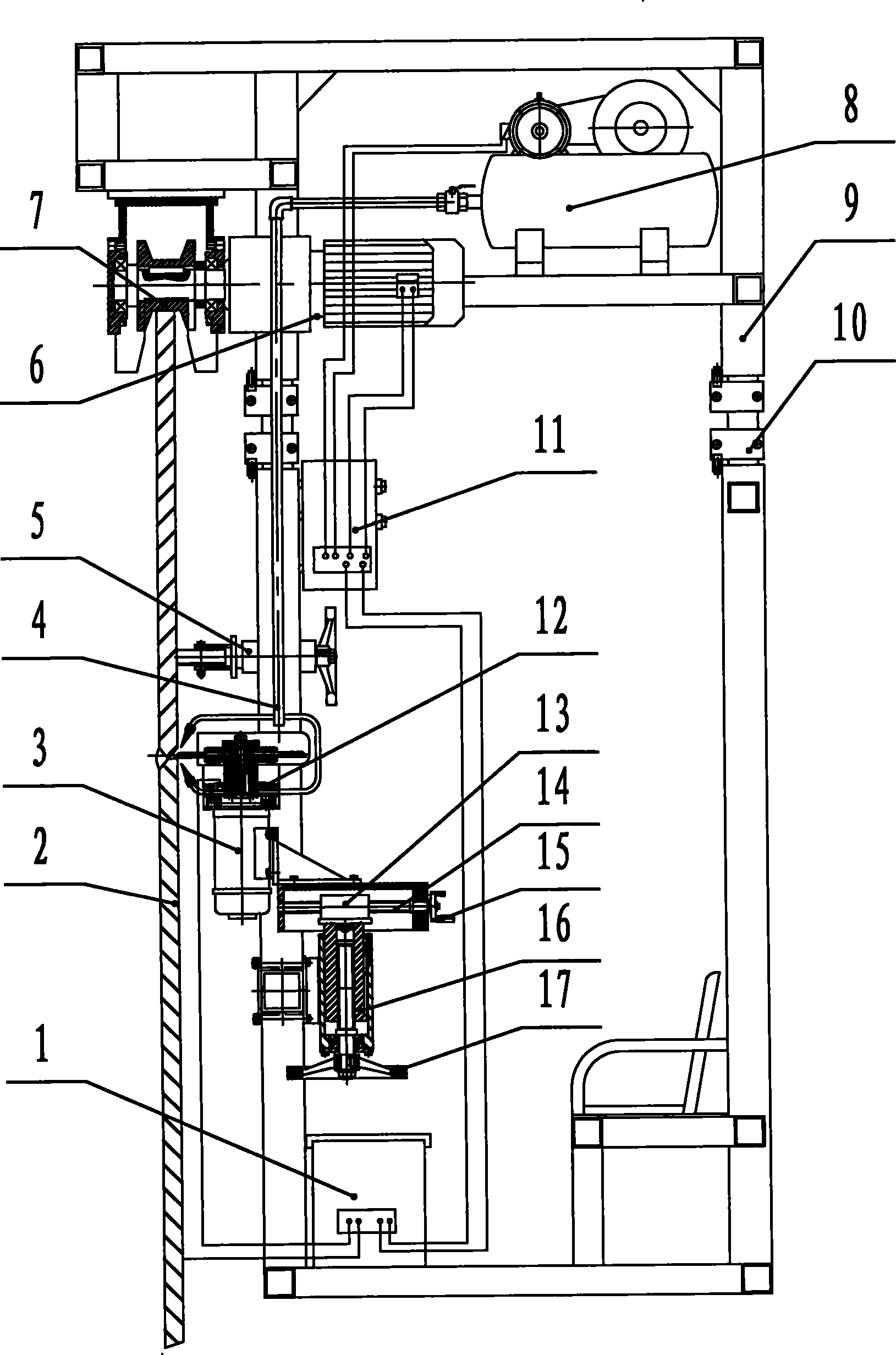
[0024] Such as figure 1 As shown, this embodiment is mainly used for cleaning the welding joints of large storage tanks. This embodiment includes a vertical frame with a frame structure. A traveling mechanism 7 that can be displaced along the top surface of the workpiece to be welded is provided on the top of the frame. The distance between the balance wheel mechanism 5 is used to adjust the distance between the frame and the workpiece, and the support frame moves smoothly; a root cleaning machine 12 is installed on the frame below the balance wheel mechanism 5; The adjusting mechanism that adjusts slide plate 16 and lateral feed slide plate 13 is installed on the drive motor 3 on the frame (wherein the axis of longitudinal adjustment slide plate 16 is parallel to the vertical bar that constitutes frame, and is fixedly connected with frame by connecting piece , the transverse feed slide plate 13 is installed on the end of the longitudinal adjustment slide plate 16, and the ax...

Embodiment 2

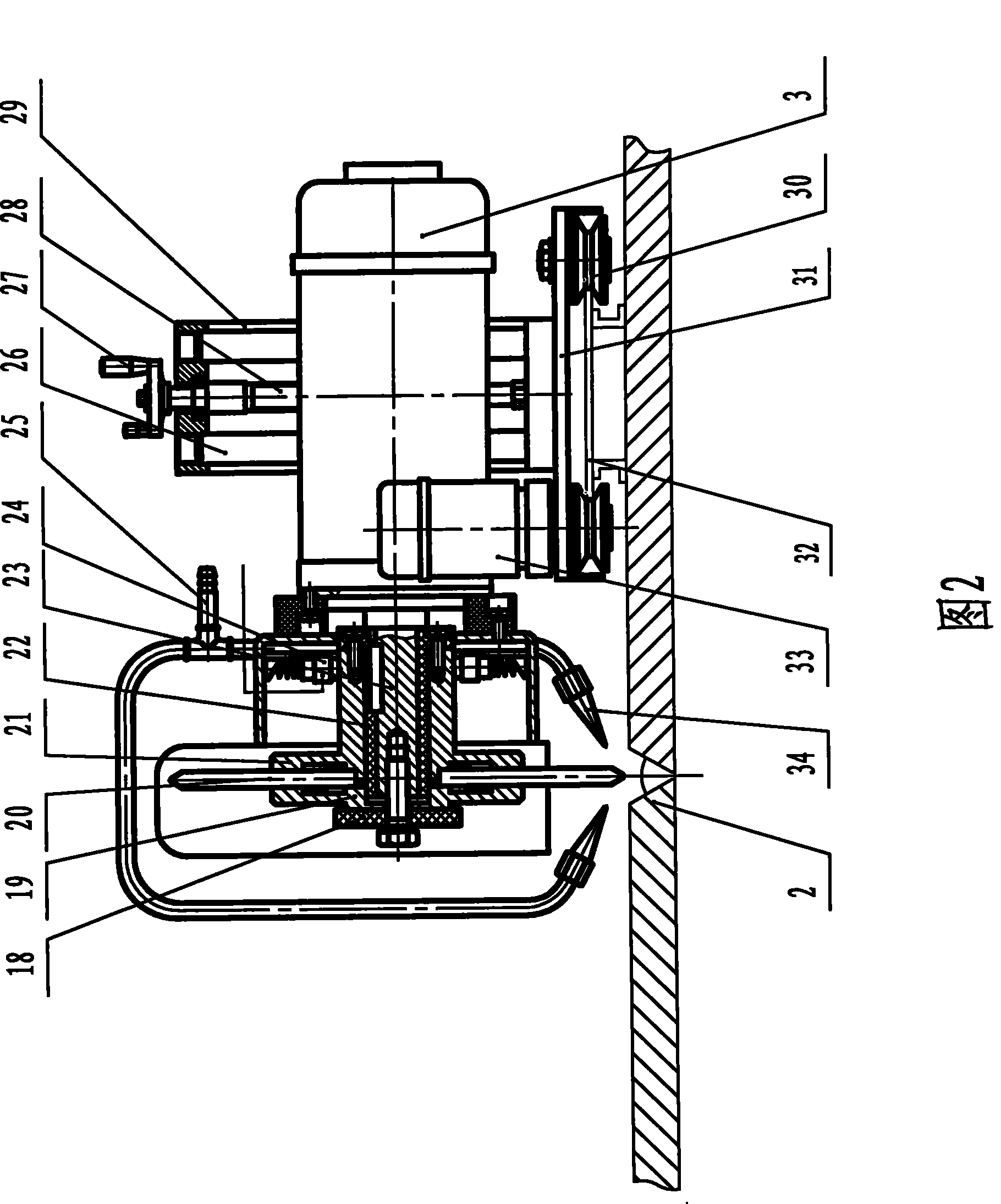
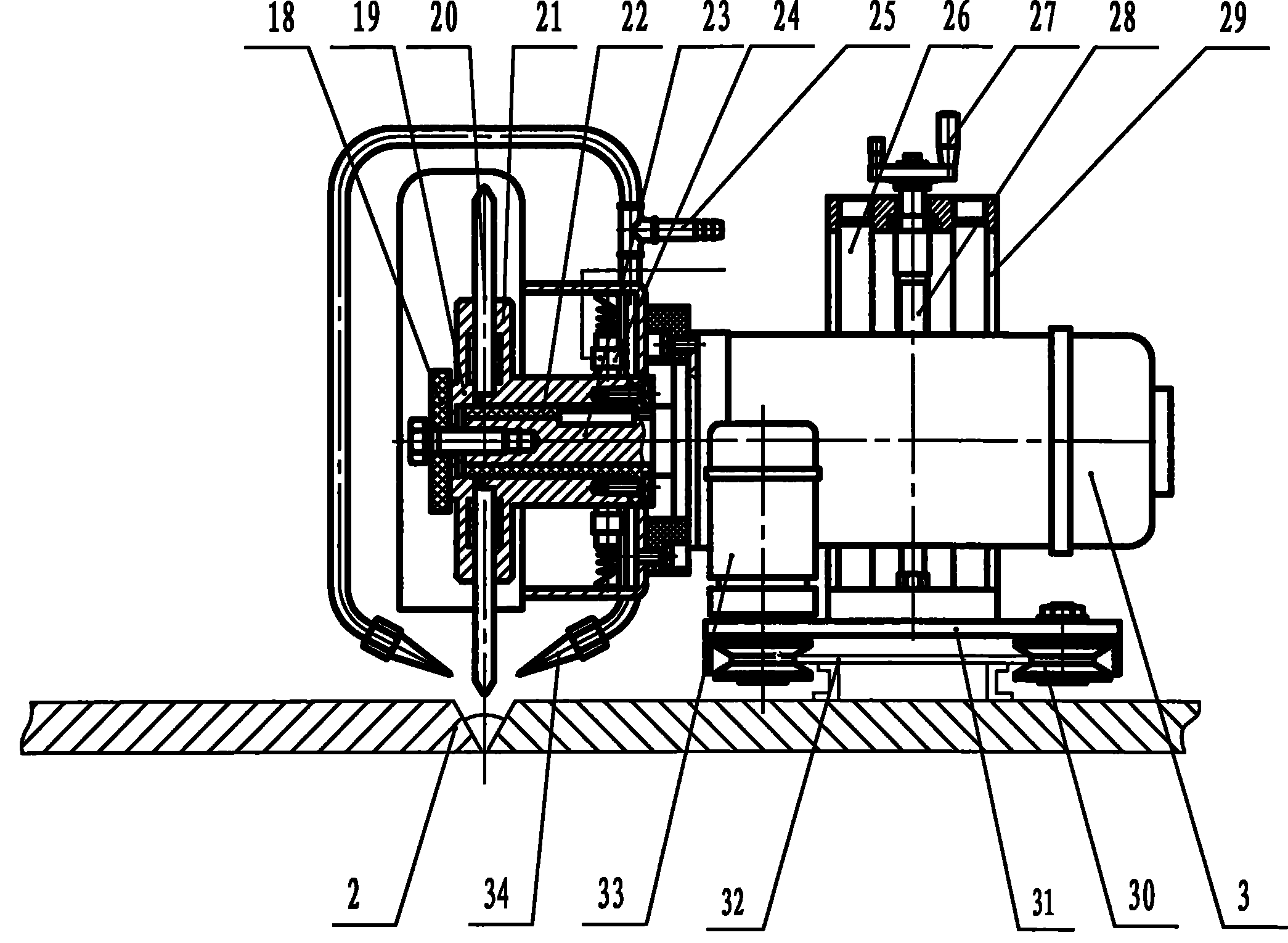
[0030] Such as figure 2 As shown, this embodiment is mainly used for cleaning the roots of welded joints of pipelines and containers, and the structure of the root cleaning machine 12 in this embodiment is the same as that of Embodiment 1. The difference between the two embodiments is that: the drive motor 3 of the root cleaner 12 is installed on the frame 31 through an adjustment mechanism composed of a transverse feed slide 29; wherein, the frame 31 is a plate structure, and The frame 31 is provided with a traveling mechanism that is formed by a sheave 30 driven by a motor 33 that is matched with the rail frame 32, and the horizontal feed slide plate 29 is installed on the frame with its axis perpendicular to the plane of the frame 31. The driving motor 3 of the root clearing machine is installed on the transverse feed slide plate 29 with its axis perpendicular to the transverse feed slide plate 29 axis. Bar 28 drives the scheme of root clearing machine 12 lateral feeds. ...


PUM


Abstract

A rotary-electrode electric-fusion welding seam automatic back gouging device is characterized in that the device includes a machine frame with a travel mechanism and a back gouging machine (12) arranged on the machine frame via a regulating mechanism; the back gouging machine (12) includes an actuating motor which is combined with the regulating mechanism, an insulating bush (22) and a hollow shaft (21) which are sequentially sleeved on an output shaft (23) of the actuating motor in a stationary fit manner, an electrode plate (20) which is sleeved on the insulating bush (22) and is press-mounted at the front end of the hollow shaft (21) via a press plate, two electric brushes which are mounted outside the hollow shaft and are contacted with the hollow shaft in a movable fit manner, and agas spout with the portal-type structure which is fixed on the front end cover of the actuating motor in the manner of crossing the electrode plate (20), wherein two nozzles (34) are respectively arranged at two lower ports of the gas spout, the spouting vents of the nozzles (34) are tilted downwards and arranged on the two sides of the electrode plate (20) in an opposite manner, and the gas spout is connected with a compressed air supply via an air inlet pipe opening (25).

Description

technical field [0001] The invention relates to the field of welding technology, in particular to an automatic root cleaning device for a rotating electrode electrofusion weld seam. Background technique [0002] With the large-scale and rapid development of the modern petroleum industry, the welding technology of long-distance pipelines and large storage tanks is developing in the direction of high quality, low cost and high efficiency. The welding technology is constantly improving, and the degree of automation is getting higher and higher. , The quality and speed requirements for root cleaning of weld seams are also getting higher and higher. [0003] In the manufacturing and installation process of long-distance pipelines, large storage tanks, and pressure vessels, welding is a key link, and the quality of welding directly affects the service life and safety of products. In order to ensure the welding quality, the root cleaning treatment in the construction is an importa...

Claims


Application Information

Patent Timeline
Patent Type & Authority Patents(China)
IPC IPC(8): B23K9/013B23K9/12
Inventor 孙克刚陈连山钱明亮高豹华杨文会金鹏
Owner CHINA PETROLEUM PIPELINE BUREAU
Learn More