
A stencil-pressing roller mechanism for a carton printing die-cutting machine

A carton printing and die-cutting machine technology, which is applied to printing machines, rotary printing machines, printing, etc., can solve the problems of high frequency of use of die rollers, complex structure of die rollers, and difficult maintenance of faults, so as to improve work efficiency, The effect of strong adaptability and convenient operation

Active Publication Date: 2016-09-07
SHANDONG SENY MACHINERY
View PDF11 Cites 0 Cited by
  • Summary
  • Abstract
  • Description
  • Claims
  • Application Information

AI Technical Summary

Problems solved by technology

[0002] Nowadays, carton printing die-cutting machines are widely used in carton packaging manufacturers. At present, the die-cutting pressure adjustment mechanism of carton printing die-cutting machines is usually placed on the die roller. Maintenance, and there is no die-cutting work switching mechanism, resulting in serious damage to the die-cutting knife in the idling state of the die-cutting machine, and the high frequency of use of the die-cutting roller, frequent replacement of the die-cutting roller with a complex structure will also lead to a decrease in production costs improve
In the production process, it is sometimes necessary to adjust the axial position of the die-cutting roller. This requires the die-cutting knife to be removed and re-fixed.

Method used


Image

  • A stencil-pressing roller mechanism for a carton printing die-cutting machine
  • A stencil-pressing roller mechanism for a carton printing die-cutting machine
  • A stencil-pressing roller mechanism for a carton printing die-cutting machine

Examples


Embodiment Construction

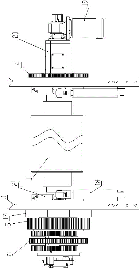
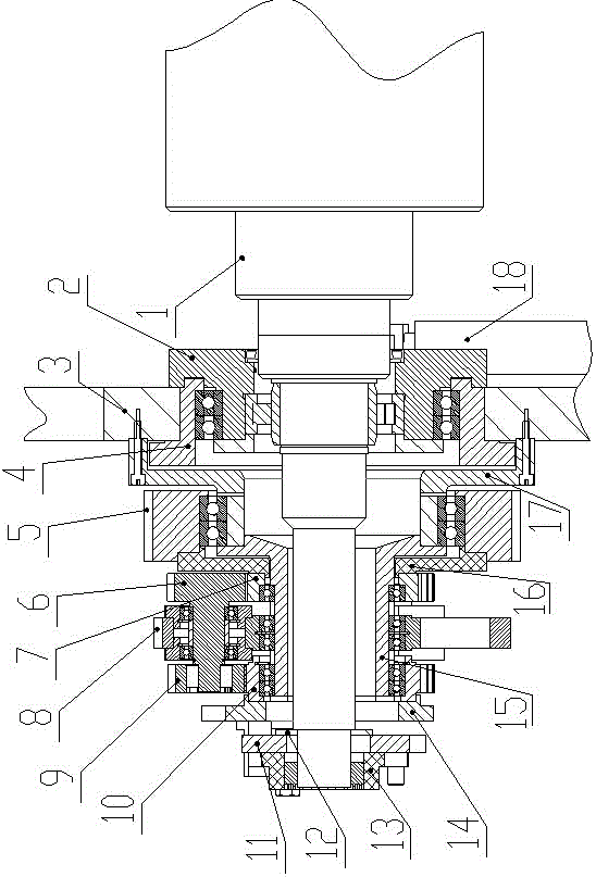
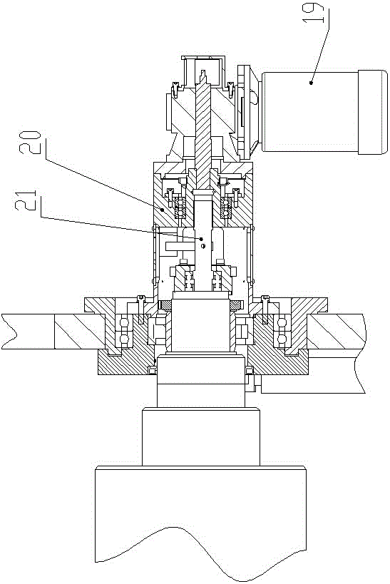
[0019] Such as figure 1 , figure 2 , image 3 As shown, the utility model provides a carton printing die-cutting machine stamping roller mechanism, including two side wallboards 3 and the central rotary connection of the plate roller 1, the upper part is provided with stamping rollers and other rollers, through the transmission mechanism to drive each Roller rotation, the improvement is that the shaft of version roller 1 and the wall panels on both sides are respectively rotated and connected to eccentric sleeves 2, and eccentric sleeves 2 are respectively hinged with cylinders 18 to control their rotation. When the arm of the cylinder 18 is stretched out, under the action of the eccentric sleeve 2, the axis center of the plate roller 1 moves up, and the shaft is connected to the power through the half coupling 13. At this time, it is in working condition. When the arm of the cylinder 18 retracts , the shaft center of version roller 1 moves down, and the shaft is disconnect...


PUM


Abstract

The invention provides a pressing die printing roller mechanism of a carton printing die-cutting machine. The pressing die printing roller mechanism comprises wallboards on two sides and a printing roller which is connected in a rotating mode in the middle, eccentric bushings are connected between a shaft of the printing roller and the two wallboards in a rotating mode, each eccentric bushing is connected with an air cylinder in a hinged mode, and each air cylinder controls rotation of the corresponding eccentric bushing; eccentric bushing bases are connected between the eccentric bushings and the wallboards in a rotating mode; a planet wheel set mechanism adjusting the phase of the printing roller is arranged on the outer side of the wallboard on one side, a speed reduction motor on the outer side of the wallboard on the other side is fixedly connected with a support, and a mechanism converting rotation of the shaft into axial movement of a screw rod is arranged in the support. The pressing die printing roller mechanism has the advantages that the four functions of die-cutting printing roller phase adjustment, die-cutting pressure adjustment, printing roller axial adjustment and die-cutting working state switching are integrated, state switching is very convenient, the structure is compact, and pressure adjustment is simple and accurate.

Description

technical field [0001] The invention relates to a carton printing die-cutting machine, in particular to a carton printing die-cutting machine press plate roller mechanism. Background technique [0002] Nowadays, carton printing die-cutting machines are widely used in carton packaging manufacturers. At present, the die-cutting pressure adjustment mechanism of carton printing die-cutting machines is usually placed on the die-cutting roller. Such a structure makes the structure of the die-cutting roller more complicated and it is not easy to fail Maintenance, and there is no die-cutting work switching mechanism, resulting in serious damage to the die-cutting knife in the idling state of the die-cutting machine, and the high frequency of use of the die-cutting roller, frequent replacement of the die-cutting roller with a complex structure will also lead to a decrease in production costs improve. Sometimes it is necessary to adjust the axial position of the molding roller during...

Claims


Application Information

Patent Timeline
Patent Type & Authority Patents(China)
IPC IPC(8): B41F19/00
Inventor 杜冬任开文
Owner SHANDONG SENY MACHINERY
Learn More