Dual-drive horizontal drive mechanism of stacking machine

A technology of horizontal drive and stacker, applied in the field of stacker, can solve the problems of increasing adhesion, increasing axle load, wheel grinding loss circle, etc., to increase friction, improve driving friction and braking torque improved effect

Inactive Publication Date: 2015-04-01
WUXI ZHONGDING INTEGRATION TECH CO LTD
View PDF7 Cites 7 Cited by
  • Summary
  • Abstract
  • Description
  • Claims
  • Application Information

AI Technical Summary

Problems solved by technology

[0003] At present, the existing stackers are all driven by a motor. Such a drive makes a part of the total weight of the entire stacker shared on the drive shaft, that is, the driving wheel bears a part of the weight, and the operation of the stacker It is driven by the adhesion force of the wheel and rail, and the adhesion force is the product of the drive axle weight and the adhesion coefficient. This kind of driving method cannot concentrate all the weight on the drive shaft to increase the axle load, and then increase the adhesion force. The traditional single drive is limited by the adhesive force. When the starting acceleration and stopping deceleration increase, the wheels will slip and idle due to insufficient adhesion, which will cause the wheels and tracks to be worn. The wear of the wheels will lose their roundness, and vibration and vibration will occur during operation. Noise causes premature damage to wheels and tracks, so the acceleration and deceleration of single drive is generally only 0.6m / s 2 Left and right, it takes a lot of time to start and stop in this way, and the operation efficiency is low

Method used


Image

  • Dual-drive horizontal drive mechanism of stacking machine

Examples


Embodiment Construction

[0014] The technical solutions of the present invention will be further described below in conjunction with the accompanying drawings and through specific implementation methods.

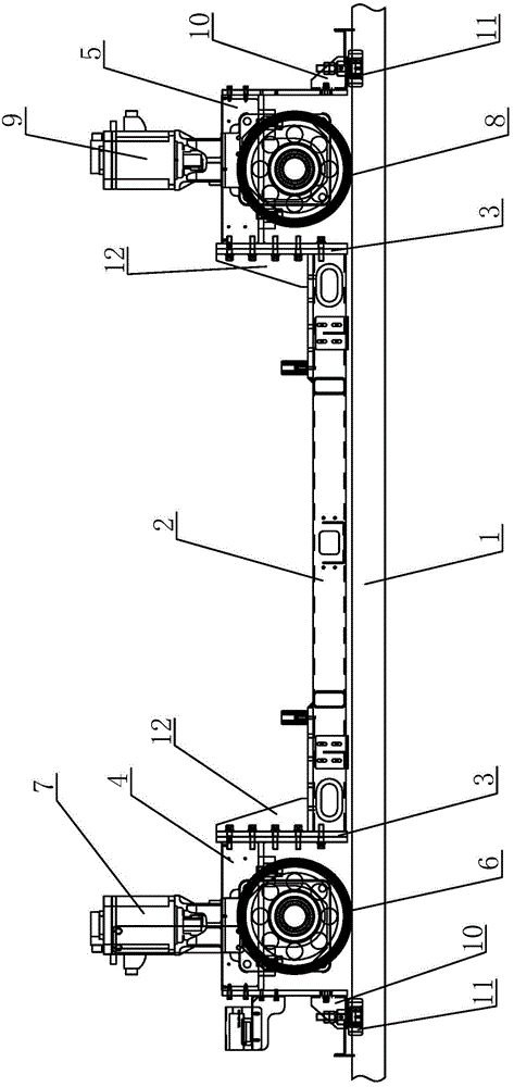
[0015] see figure 1 as shown, figure 1 It is a structural schematic diagram of the horizontal drive mechanism of the dual-drive stacker provided in Embodiment 1 of the present invention.

[0016] In this embodiment, a double-drive type stacker horizontal driving mechanism includes a track 1 and a stacker running mechanism arranged on the track 1, wherein the stacker running mechanism includes a lower beam 2, and the lower beam 2 The two ends of each have a first driving frame 4 and a second driving frame 5 through the connecting plate 3, the first driving frame 4 is provided with a first driving wheel 6 and a first driving motor 7, and the first driving motor 7 The first drive wheel 6 is driven to walk through the reducer, and the second drive frame 5 is provided with a second drive wheel 8 and a ...


PUM


Abstract

The invention discloses a dual-drive horizontal drive mechanism of a stacking machine. The dual-drive horizontal drive mechanism comprises a rail and a travelling mechanism of the stacking machine; the travelling mechanism disposed on the rail comprises a lower beam; two ends of the lower beam are connected with a first drive rack and a second drive rack through connecting plates, respectively; a first drive wheel and a first drive motor are disposed on the first drive rack; the first drive motor drives the first drive wheel to travel; a second drive wheel and a second drive motor are disposed on the second drive rack; the second drive motor drives the second drive wheel to travel. The dual-drive horizontal drive mechanism is in a dual-drive mode, and thus, weight of all devices is on the drive wheels; the use of synchronous control leads to increase in friction and more than double of increase in acceleration, with the wheels never skidding; additionally, single-drive power is equaled to two motors, and thus, drive friction is increased, start acceleration is increased and brake torque is increased.

Description

technical field [0001] The invention relates to a stacker, in particular to a double-drive horizontal drive mechanism of the stacker. Background technique [0002] A stacker refers to a special-purpose crane that uses a fork or a skewer to grab, carry and stack or access unit goods from high-level shelves (see unitized transportation). It is a storage device. [0003] At present, the existing stackers are all driven by a motor. Such a drive makes a part of the total weight of the entire stacker shared on the drive shaft, that is, the driving wheel bears a part of the weight, and the operation of the stacker It is driven by the adhesion force of the wheel and rail, and the adhesion force is the product of the drive axle weight and the adhesion coefficient. This kind of driving method cannot concentrate all the weight on the drive shaft to increase the axle load, and then increase the adhesion force. The traditional single drive is limited by the adhesive force. When the sta...

Claims


Application Information

Patent Timeline
Patent Type & Authority Applications(China)
IPC IPC(8): B66F9/075B66F9/06
CPCB66F9/07572B66F9/072
Inventor 涂会兵王佳玮周伟新
Owner WUXI ZHONGDING INTEGRATION TECH CO LTD
Why Eureka
Try Eureka