Pressure reducing valve device in water supply hydraulic system

A technology of hydraulic system and pressure reducing valve, applied in the field of pressure reducing valve device, can solve the problems of large volume, complex internal structure, unsuitable for pipeline installation, etc., and achieve the effect of small volume, simple structure, and reliable safety performance.

Active Publication Date: 2016-08-24
GUANGZHOU XINXING VALVE IND CO LTD
View PDF5 Cites 0 Cited by
  • Summary
  • Abstract
  • Description
  • Claims
  • Application Information

AI Technical Summary

Problems solved by technology

However, the pressure reducing valves connected to the existing pipelines, such as diaphragm pressure reducing valves, have complex internal structures and large volumes, and are not suitable for installation on pipelines on floors. The number of settings on the floor is often limited, but if the floor is too high, the pressure to be output is high. If there is not a sufficient number of decompression equipment, there are still potential safety hazards

Method used


Image

  • Pressure reducing valve device in water supply hydraulic system

Examples


Embodiment Construction

[0011] Below in conjunction with accompanying drawing and specific embodiment the present invention will be described in further detail:

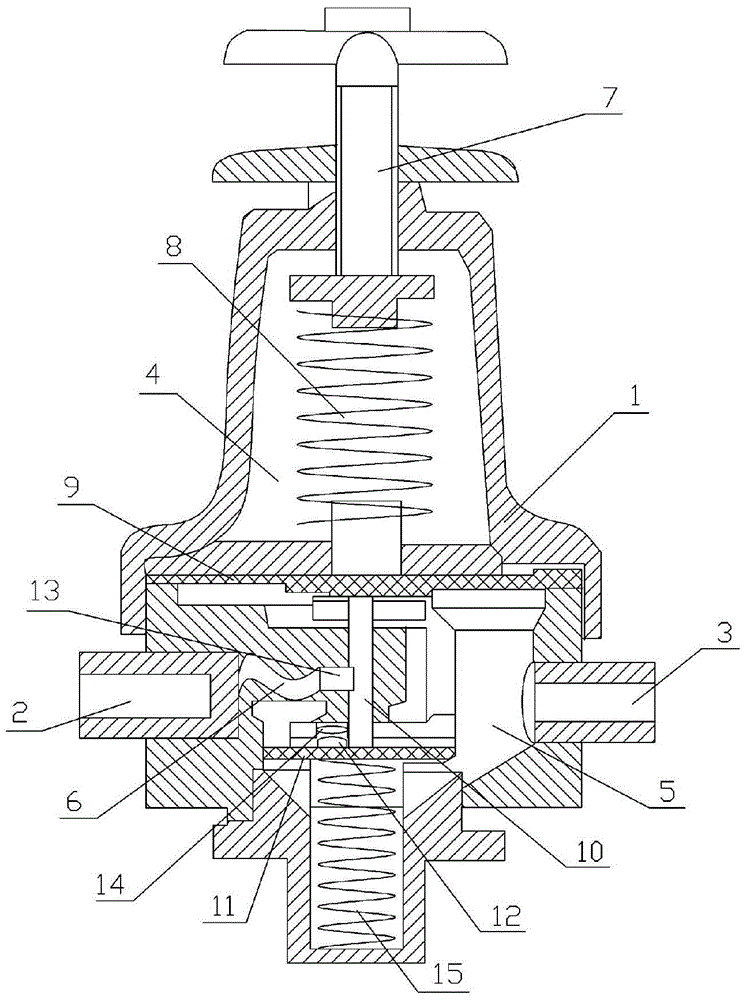
[0012] The reference signs in the drawings of the specification include: pressure reducing valve body 1, water inlet pipe 2, water outlet pipe 3, inner cavity body 4, water storage bin 5, channel 6, handle 7, coil spring 8, diaphragm 9, pole 10, elastic clamping plate 11, rubber plate 12, nozzle pipe 13, air inlet nozzle 14, extension spring 15.

[0013] Such as figure 1 As shown, the pressure reducing valve device in the water supply hydraulic system includes a pressure reducing valve body 1, the two ends of the pressure reducing valve body 1 are respectively provided with a water inlet pipe 2 and a water outlet pipe 3, and the pressure reducing valve body 1 is provided with an inner cavity Cavity 4, water storage bin 5 and "S" shaped channel 6, water storage bin 5 communicates with water outlet pipe 3, the top of pressure reducing valve ...


PUM


Abstract

The invention discloses a pressure reducing valve device in a water supply hydraulic system. The pressure reducing valve device comprises a pressure reducing valve body. A water inlet pipeline and a water outlet pipeline are respectively arranged at two ends of the pressure reducing valve body, an inner cavity, a water storage bin and a channel are arranged in the pressure reducing valve body, the water storage bin is communicated with the water outlet pipeline, a handle which runs through the inner cavity is arranged on the top of the pressure reducing valve body, a spiral spring is vertically arranged in the inner cavity, one end of the spiral spring is connected to the handle, a membrane is connected to the other end of the spiral spring, a cylindrical bar which is vertically arranged is connected to the bottom of the membrane, an elastic clamp plate is connected with the cylindrical bar, a rubber plate is arranged on the elastic clamp plate, a tension spring which is fixed onto the wall of the inner cavity is connected to the bottom of the elastic clamp plate, and a spray pipe is communicated with the water inlet pipeline via the channel in the pressure reducing valve body. The pressure reducing valve device in the water supply hydraulic system has the advantages of simple structure, small size and excellent safety performance.

Description

technical field [0001] The water supply hydraulic equipment of the present invention particularly relates to a pressure reducing valve device in a water supply hydraulic system. Background technique [0002] With the acceleration of the urbanization process to save land, the floors gradually increase, which undoubtedly brings a lot of inconvenience to the urban water supply, which requires the secondary water supply of the water supply pump group. However, the water supply pump group is opened and stopped, accompanied by valve The opening and closing of the water hammer will cause water hammer phenomenon in the tap water. The water hammer may be several times, ten times, or even dozens of times greater than the water supply pressure, so the consequences of this phenomenon will be very serious. Therefore, the pipeline uses A special decompression device is very necessary; the decompression device not only has a decompression effect, but also has a pressure stabilizing effect....

Claims


Application Information

Patent Timeline
Patent Type & Authority Patents(China)
IPC IPC(8): F16K47/08
CPCF16K47/08
Inventor 曾国辉
Owner GUANGZHOU XINXING VALVE IND CO LTD
Why Eureka
Try Eureka