Method for diagnosing and positioning faults of two position sensors of four-phase switch magnetic resistance motor

A sensor fault, reluctance motor technology, applied in the direction of motor generator testing, instruments, measuring devices, etc., can solve problems such as loss of edge pulses of position sensor output signals, inappropriate operation of switched reluctance motors with speed changes, sensor failures, etc. , to achieve the effect of extensive engineering application value, reliable diagnosis method, and avoid misdiagnosis

Inactive Publication Date: 2015-04-01
CHINA UNIV OF MINING & TECH
View PDF4 Cites 7 Cited by
  • Summary
  • Abstract
  • Description
  • Claims
  • Application Information

AI Technical Summary

Problems solved by technology

However, due to dust, collision and other reasons, the commonly used photoelectric, magnetoelectric, and electromagnetic position sensors will fail, resulting in the loss of edge pulses of the output signal of the position sensor after the failure.
If the position sensor fails and fails, the commutation of the switched reluctance motor will fail, which will affect the reliable operation of the switched reluctance motor. Therefore, it is extremely important to diagnose and locate the position sensor.
The traditional fault diagnosis method based on interval time and fault diagnosis method based on edge capture is only suitable for the constant speed operation state of the switched reluctance motor, and is not suitable for the speed change operation of the switched reluctance motor.

Method used


Image

  • Method for diagnosing and positioning faults of two position sensors of four-phase switch magnetic resistance motor
  • Method for diagnosing and positioning faults of two position sensors of four-phase switch magnetic resistance motor
  • Method for diagnosing and positioning faults of two position sensors of four-phase switch magnetic resistance motor

Examples


Embodiment Construction

[0023] An embodiment of the present invention will be further described below in conjunction with accompanying drawing:

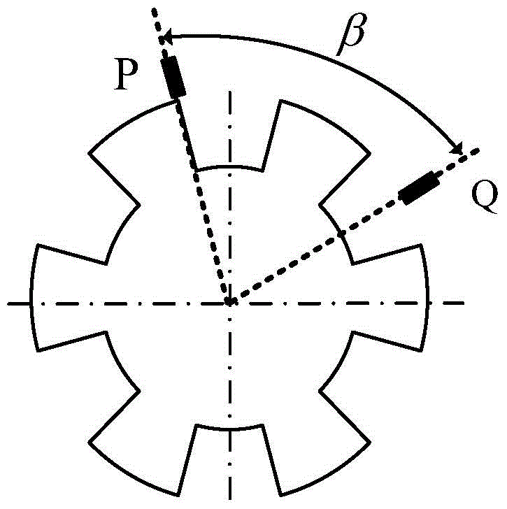
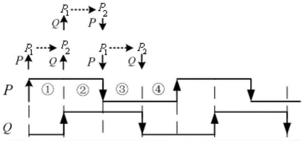
[0024] figure 1 Shown is a schematic diagram of the installation of two position sensors P and Q of a four-phase 8 / 6 structure switched reluctance motor, and the installation angle β of the two position sensors P and Q is 75 degrees. The resulting output signal of the position sensor is as follows: figure 2 As shown, the output signal phase of the switched reluctance motor position sensor P is earlier than the output signal phase of the position sensor Q in time; the rising edge of the output signal of the position sensor P to the rising edge of the output signal of the position sensor Q is the interval ①, The rising edge of the output signal of Q to the falling edge of the output signal of the position sensor P is the interval ②, the falling edge of the output signal of the position sensor P to the falling edge of the output signal of the position sensor ...


PUM


Abstract

The invention discloses a method for diagnosing and positioning faults of two position sensors of a four-phase switch magnetic resistance motor. The method is suitable for diagnosing and positioning the faults of the two position sensors of a rotary or linear switch magnetic resistance motor with four and quadruple of four phases and a plurality of topology structures. The method comprises the following steps: judging whether position sensor faults exist according to the sequence of two adjacent edge pulses of output signals of the two position sensors, setting a fault diagnosing and buffering zone, avoiding the occurrence of incorrect diagnosis, and positioning the faults of the position sensors by distinguishing the output signals of the position sensors of an edge pulse source; the method can be used for diagnosing and positioning faults of one position sensor or the two position sensors; diagnosing and positioning results are not influenced by the speed change of constant speed, acceleration and deceleration of the motor. The diagnostic method is reliable, is high in practicability and has wide engineering application value.

Description

technical field [0001] The invention relates to a fault diagnosis and positioning method for two position sensors of a four-phase switched reluctance motor, especially suitable for two position sensors of four and four multiple phases, various topological structures, rotary or linear switched reluctance motors fault diagnosis and location. Background technique [0002] In the rotary or linear switched reluctance motor system, the output signal of the position sensor provides the basis for speed calculation and motor commutation, which plays an extremely important role in the reliable operation of the rotary or linear switched reluctance motor system. However, due to dust, collision and other reasons, the commonly used photoelectric, magnetoelectric, and electromagnetic position sensors will fail, resulting in the loss of edge pulses of the output signal of the position sensor after the failure. If the position sensor fails and fails, the commutation of the switched reluctan...

Claims


Application Information

Patent Timeline
Patent Type & Authority Applications(China)
IPC IPC(8): G01R35/00G01R31/34
CPCG01R31/34H02P6/12
Inventor 陈昊韩国强程鹤王千龙王青王星
Owner CHINA UNIV OF MINING & TECH
Why Eureka
Try Eureka