Method and diagnostic unit for diagnosing differential pressure sensor

A sensor and pressure difference technology, which is applied to the pressure difference measurement between multiple valves, the diagnostic device of the exhaust gas treatment device, the instrument, etc., can solve the problems that the identification of the connecting parts cannot be realized, so as to reduce the risk and realize the identification and accurate positioning, the effect of time gradient increase

Active Publication Date: 2015-11-25
ROBERT BOSCH GMBH
View PDF8 Cites 17 Cited by
  • Summary
  • Abstract
  • Description
  • Claims
  • Application Information

AI Technical Summary

Problems solved by technology

[0012] The method does not enable th...

Method used


Image

  • Method and diagnostic unit for diagnosing differential pressure sensor
  • Method and diagnostic unit for diagnosing differential pressure sensor
  • Method and diagnostic unit for diagnosing differential pressure sensor

Examples


Embodiment Construction

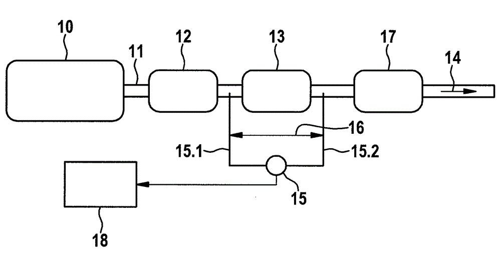
[0039] figure 1 The technical field in which the invention can be used is shown in a schematic diagram in an embodiment variant. In this case, the illustration is limited to the components necessary for the description of the invention. An internal combustion engine 10 is shown as an example, which is embodied as an Otto motor, wherein the exhaust gas of the internal combustion engine 10 is discharged via an exhaust gas line 11 . A multi-stage exhaust gas cleaning system is arranged in the exhaust gas line 11 . Furthermore, a catalytic converter 12 embodied as a three-way catalytic converter and a particle filter 13 are arranged as exhaust gas aftertreatment units along the exhaust gas line 11 in the flow direction of the exhaust gas flow 14 . A silencer 17 is arranged downstream of the particle filter 13 .

[0040] For diagnosing the particle filter 13 , a differential pressure sensor 15 is connected, with which a pressure difference between the filter inlet and the filter...


PUM


Abstract

The invention relates to a method for diagnosing a differential pressure sensor which determines a differential pressure across a arranged in an exhaust section exhaust gas treatment unit of an exhaust gas purification system of an internal combustion engine and which is connected to a front connection to the exhaust line prior to the exhaust gas after treatment unit and a rear connection to the exhaust line downstream of the exhaust gas after treatment unit wherein the diagnosis is made based on a comparison of a measured temporal differential pressure gradient the measured differential pressure due to a change in exhaust pressure before the exhaust gas after treatment unit with an expected temporal differential pressure gradient an expected differential pressure . It is envisaged that a correlation between a profile of the measured differential pressure gradient with a gradient of the expected differential pressure gradient is determined and that, for a high correlation to an intact differential pressure sensor with intact terminals and at a low correlation to a faulty differential pressure sensor or to one or two defective terminals of the differential pressure sensor is closed. The invention further relates to a diagnostic unit for carrying out the inventive method. The method and diagnostic unit enables the reliable detection of various errors of a differential pressure sensor.

Description

technical field [0001] The invention relates to a method for diagnosing a differential pressure sensor which determines the differential pressure across an exhaust gas aftertreatment unit of an exhaust gas cleaning system of an internal combustion engine arranged in an exhaust gas line and which uses a previous A connecting piece is connected to the exhaust gas line upstream of the exhaust gas aftertreatment unit and connected to the exhaust gas line downstream of the exhaust gas aftertreatment unit with a rear connecting piece, wherein the diagnosis is based on changes in the exhaust gas pressure upstream of the exhaust gas aftertreatment unit The ratio of the measured time differential pressure gradient of the measured pressure differential to the expected time differential pressure gradient of the expected differential pressure is performed. [0002] The invention also relates to a diagnostic unit for diagnosing a pressure sensor for determining a differential pressure acro...

Claims


Application Information

Patent Timeline
IPC IPC(8): F01N11/00G01L13/00
CPCF01N11/00F01N11/002F01N2560/08F01N2900/0422F01N2900/1406G01L23/24Y02T10/40
Inventor T.蔡因连运捷
Owner ROBERT BOSCH GMBH
Why Eureka
Try Eureka