
Failure diagnosis apparatus of hybrid vehicle

a hybrid vehicle and failure diagnosis technology, applied in the direction of engines, machines/engines, propulsion using engine-driven generators, etc., can solve the problems of failure diagnosis system making an error determination, failure diagnosis with low accuracy, failure diagnosis system not responding to a change in use, etc., to prevent the error of diagnosis

Active Publication Date: 2015-01-29
TOYOTA JIDOSHA KK
View PDF11 Cites 15 Cited by
  • Summary
  • Abstract
  • Description
  • Claims
  • Application Information

AI Technical Summary

Benefits of technology

The invention relates to a failure diagnosis apparatus for hybrid vehicles which includes an internal combustion engine, a rotary electric machine, and an electric power storage device. The apparatus is designed to diagnose failures of the internal combustion engine and prevent system or driver-based forcible stops of the internal combustion engine based on an erroneous diagnosis. The diagnosis requirement for detecting failures of the internal combustion engine during engine-operation-electric-power supply is different from the diagnosis requirement during engine-normal operation to prevent driver anxiety or inappropriate diagnosis. The apparatus also considers execution history of previous engine-operation-electric-power supply to change the diagnosis requirement and prevent failures of the internal combustion engine during emergency electric power supply. The technical effects of the invention include improved reliability and safety of the hybrid vehicle and improved driving experience.

Problems solved by technology

Consequently, the failure diagnosis system of the related art does not respond to a change in the use of the internal combustion engine resulting from technological advancement in recent years.
Accordingly, if no countermeasure is taken, when the external electric power supply is to be executed in such a hybrid vehicle, there is a possibility that the failure diagnosis system makes an erroneous determination.
Therefore, the failure diagnosis with low accuracy can be a factor that restricts opportunity for the external electric power supply.
In addition, a failure history is often stored in various computer devices that control the vehicle.
The storage of the failure detection history based on an inaccurate failure diagnosis is not desirable for the owner of the vehicle.

Method used


Image

  • Failure diagnosis apparatus of hybrid vehicle
  • Failure diagnosis apparatus of hybrid vehicle
  • Failure diagnosis apparatus of hybrid vehicle

Examples


second embodiment

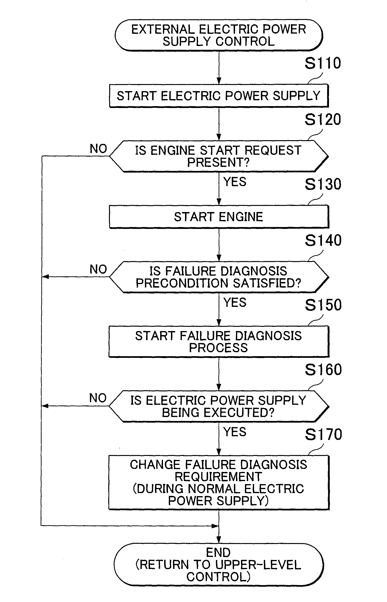
[0123]Next, a description will be given of an engine start control as a second embodiment of the invention with reference to FIG. 6. FIG. 6 is a flowchart of the engine start control. Similarly to the external electric power supply control, the engine start control is a sub-routine. The engine start control is executed when the start of the engine 200 is requested through an ignition operation or a start button operation. This start request is different from the start request in the external electric power supply.

[0124]A description will be given hereinbelow with reference to FIG. 6. The ECU 100 starts the engine 200 (Step S210). Subsequently, it is determined whether or not the failure diagnosis precondition is satisfied (Step S220). It is determined whether or not the failure diagnosis precondition is satisfied by the same method as that in the external electric power supply control according to the first embodiment. When the failure diagnosis precondition is not satisfied (Step S...


PUM


Abstract

A failure diagnosis apparatus comprises a controller that is configured to execute a failure diagnosis process of the internal combustion engine based on a predetermined diagnosis requirement. The diagnosis requirement in a case where engine-operation-electric-power supply is executed is made different from the diagnosis requirement in a case where engine-normal-operation is executed such that a failure of the internal combustion engine in the case where the engine-operation-electric-power supply is executed is less likely to be detected or the failure of the internal combustion engine is less likely to be recognized by a driver than in the case where the engine-normal operation is executed.

Description

BACKGROUND OF THE INVENTION[0001]1. Field of the Invention[0002]The invention relates to a failure diagnosis apparatus of a hybrid vehicle.[0003]2. Description of Related Art[0004]Japanese Patent Application Publication No. 2001-231106 (JP-2001-231106 A) discloses a hybrid vehicle capable of external electric power supply. The hybrid vehicle disclosed in JP-2001-231106 A is capable of generating electric power by utilizing an engine output during stop of the vehicle. In addition, the hybrid vehicle disclosed in JP-2001-231106 A is capable of transmitting the generated electric power to the outside of the vehicle.[0005]There is proposed a technique in which a threshold value of SOC_of a battery used for determining whether to start or stop an engine during external electric power supply is made different from a threshold value of SOC of the battery while the vehicle is running (see Japanese Patent Application Publication No. 2008-247252 (JP-2008-247252 A)).[0006]In addition, there is...

Claims


Application Information

Patent Timeline
Patent Type & Authority Applications(United States)
IPC IPC(8): B60W20/00B60K6/445F02D41/22F02D41/24B60L50/10B60L50/15B60L50/16
CPCB60W20/50F02D41/2429Y10S903/902F02D41/22B60K6/445B60K6/365B60L1/006B60L3/0023B60W50/0098B60W2050/0075B60W2050/0083B60W2510/0676B60W2510/068B60L50/10B60L50/61B60W2556/10F02D2200/021F02N11/04Y02T10/62Y02T10/70Y02T10/7072B60W20/00B60W50/0205B60W50/04
Inventor FUSHIKI, SHUNSUKEYAMAZAKI, MAKOTOFUKUI, KEITA
Owner TOYOTA JIDOSHA KK
Learn More