
Constant acceleration and constant deceleration curve components of cam profile generator

A cam profile, iso-acceleration technology, applied in the direction of instruments, educational appliances, teaching models, etc., can solve problems such as not easy, to achieve the effect of simple and clear teaching, strong demonstration, promoting enthusiasm and creativity

Inactive Publication Date: 2017-01-25
JIANGXI UNIV OF SCI & TECH
View PDF7 Cites 0 Cited by
  • Summary
  • Abstract
  • Description
  • Claims
  • Application Information

AI Technical Summary

Problems solved by technology

[0006] In the current teaching research, the abstract graphic method and the difficult analytical method have always been the best choice in the teaching process. No matter what kind of curve it is for, use these two methods to summarize the acceleration and deceleration curves such as cams It is not easy because for mechanical subjects, simple written expression and oral description are not conducive to learners to achieve a good learning effect. Therefore, in order to achieve a better teaching effect, the acceleration and deceleration curves of the cam In the process of understanding, it is necessary to add a more intuitive, operable and demonstrative auxiliary teaching instrument to help learners have a deeper understanding of the characteristics of the acceleration and deceleration curves of cams, etc. more simple, clear, convenient and intuitive

Method used


Image

  • Constant acceleration and constant deceleration curve components of cam profile generator
  • Constant acceleration and constant deceleration curve components of cam profile generator
  • Constant acceleration and constant deceleration curve components of cam profile generator

Examples


Embodiment Construction

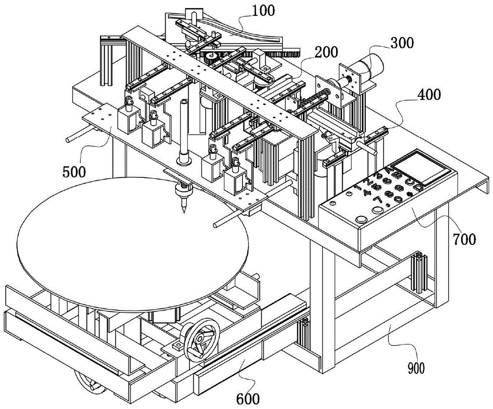
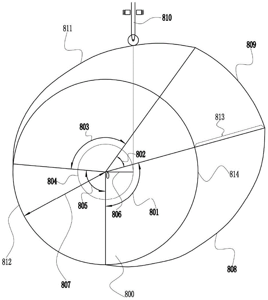
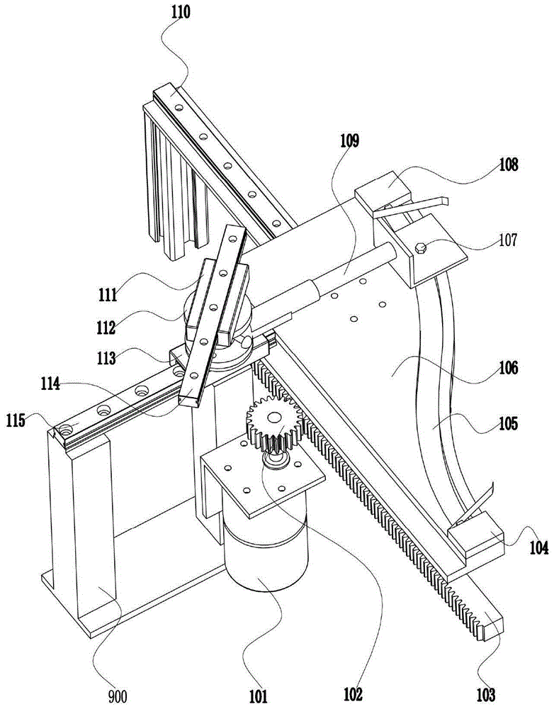
[0033] Such as Figure 1 to Figure 8 Shown, the present invention will be further described below in conjunction with accompanying drawing.

[0034] First, determine the follower 810 stroke 813h, base circle radius 807r, eccentricity 806e, and push angle 801φ 1 , Far angle of repose 802φ 2 , return angle 803φ 3 , Near angle of repose 805φ 4 The base circle radius 807 of the cam is adjusted by the base circle screw nut mechanism 607, the eccentric distance screw nut mechanism 604 adjusts the eccentricity 806, the stroke 813 is regulated by the stroke adjustment dial 112, and the prompt by the display screen 702 is followed by the numeric keypad 703 Type in the thrust angle 801φ 1 , Far angle of repose 802φ 2 , return angle 803φ 3 , Near angle of repose 805φ 4 , press the "*" key to confirm the input, press the "#" key to cancel the current operation, and A on the keyboard corresponds to the constant acceleration and deceleration curves. At this time, the display screen 7...


PUM


Abstract

The invention relates to a constant-acceleration and constant-deceleration curve assembly of a cam profile line generator. The constant-acceleration and constant-deceleration curve assembly of the cam profile line generator comprises a rack, a cam sliding rail and a lower guide rail which are mounted on the rack and are perpendicular to each other, wherein a movable cam is in sliding fit with the cam sliding rail through a sliding block; a first rack is fixed on the movable cam and is meshed with a first gear of a first motor which is fixed on the rack; a cam slot is formed in the movable cam; a first front travel switch is arranged on the front end of the cam slot; a first rear travel switch is arranged at the rear end of the cam slot; the cam groove is connected with one end of a pushing rod through a cam roller; a travel adjusting rotary plate comprises an upper plate structure and a lower plate structure; the upper plate and the lower plate can mutually rotate after a fastening part is released; the lower plate of the travel adjusting plate is connected with the other end of the pushing rod; the bottom of the lower plate is fixed on a lower sliding block; the lower sliding block slides on a lower guide rail; the upper plate of the travel adjusting rotary plate is fixed to an upper sliding block; the upper sliding block slides on an upper guide rail. The constant-acceleration and constant-deceleration curve teaching of the cam is simple and clear, convenient and intuitionistic, and is strong in demonstration property.

Description

technical field [0001] The invention relates to a teaching instrument—a cam profile generator, in particular to a constant acceleration and deceleration curve component of the cam profile generator. Background technique [0002] The cam mechanism plays an important role in the mechanical design. The cam can make the follower move in any desired way only by designing the appropriate cam profile, and the structure is simple, compact and easy to design. Therefore, it is widely used in automatic machine tools and light industrial machinery. , textile machinery, printing machinery, food machinery, packaging machinery and mechatronics products are widely used; the main function of the cam mechanism is to make the follower complete various complex movements according to the work requirements, including linear movement, swing and constant speed movement and non-uniform motion. [0003] The cam mechanism is generally a high-level mechanism composed of three components: the cam, the ...

Claims


Application Information

Patent Timeline
Patent Type & Authority Patents(China)
IPC IPC(8): G09B25/02
CPCG09B25/02
Inventor 邱小童胡发焕张根森邓聪康宇
Owner JIANGXI UNIV OF SCI & TECH
Learn More