Rapid saturable reactor

A reactor and fast technology, applied in the direction of inductors, variable inductors, circuits, etc., can solve the problems of complex process requirements and high requirements for the symmetry of the iron core of the magnetron saturable reactor, and achieve simple methods and processes. The effect of reducing symmetry requirements and adjusting the speed of response

Inactive Publication Date: 2015-04-01
SHANDONG UNIV
View PDF2 Cites 1 Cited by
  • Summary
  • Abstract
  • Description
  • Claims
  • Application Information

AI Technical Summary

Problems solved by technology

However, these two inventions have high requirements on the symmetry of the iron core of the magnetic control saturable reactor, and the process requirements are complicated.

Method used


Image

  • Rapid saturable reactor
  • Rapid saturable reactor
  • Rapid saturable reactor

Examples


Embodiment 1

[0040] The present invention will be further described below in conjunction with the accompanying drawings and embodiments.

[0041] The structure and connection method of traditional saturable reactor are as follows: figure 1 shown. Traditional saturable reactors generally have the problem of slow response, and saturable reactors need taps, and the manufacturing process is complicated.

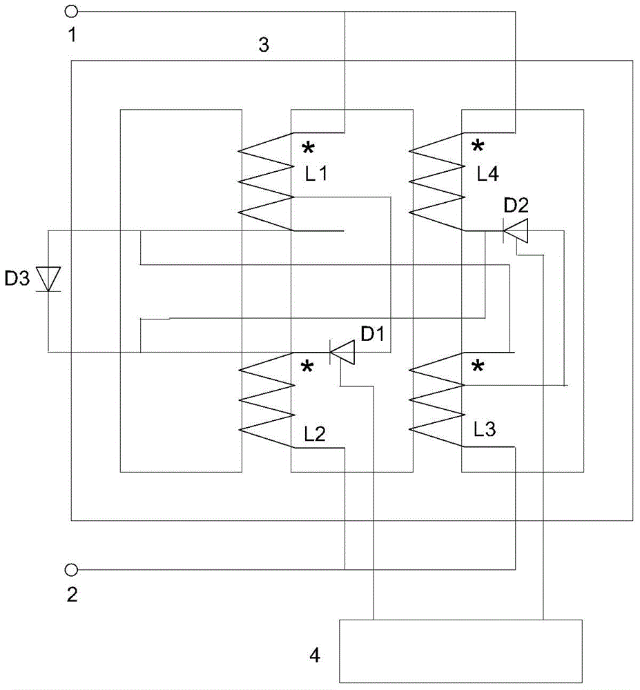
[0042] The structure and connection method of the first fast saturable reactor are as follows: figure 2 shown. Including fast saturable reactor terminal I 1, fast saturable reactor terminal II2, fast saturable reactor closed-loop iron core 3, control circuit 4. The closed-loop iron core 3 of the fast saturable reactor has at least two iron core columns; there are two iron core columns with the same cross-sectional area, both of which have DC coils and AC coils; each of these two iron core columns can at least form a Closed loop of magnetic flux in the core leg. There is a DC coil L1 and...

Embodiment 2

[0056] The present invention will be further described below in conjunction with the accompanying drawings and embodiments.

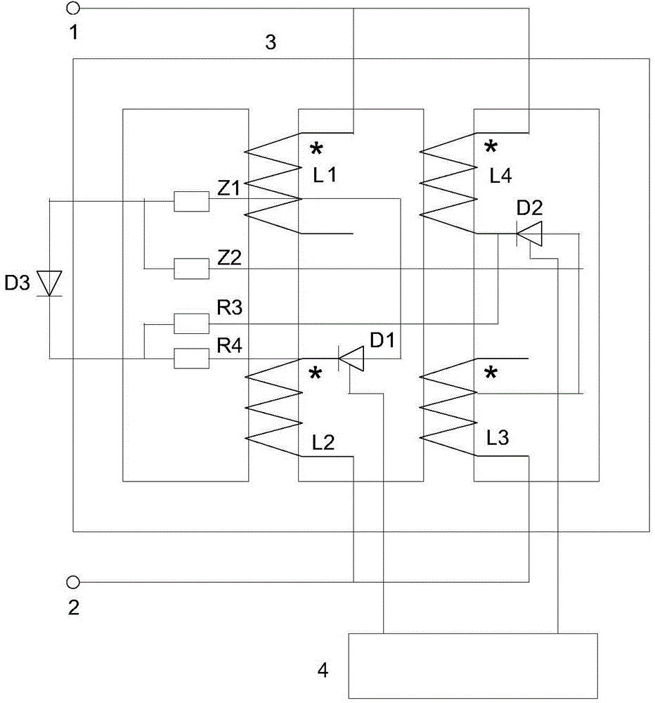
[0057] The structure and connection method of the second fast saturable reactor are as follows: image 3 shown. The parts that are the same as those in Embodiment 1 will not be repeated here. The different parts are described as follows.

[0058] Compared figure 2 and image 3 It can be seen that putting figure 2 This part of the coil from the DC coil L1 tap to the opposite end is removed, figure 2 The tap of the DC coil L1 becomes image 3 The opposite end of the DC coil L1; figure 2 The part of the DC coil L3 tapped to the end of the same name is removed, figure 2 The tap of the DC coil L3 becomes image 3 The terminal of the same name of the DC coil L3. figure 2 The DC coil L1 and the DC coil L3 respectively have three lead-out terminals, image 3 The DC coil L1 and the DC coil L3 respectively have only two lead-out terminals. The o...


PUM


Abstract

The invention relates to a rapid saturable reactor which comprises a closed loop iron core. A dotted terminal of a DC coil of an iron core limb is connected with a terminal I, and an unlike terminal of an AC coil of the iron core limb is connected with a terminal II. A dotted terminal of an AC coil of another iron core limb is connected with the terminal I, and an unlike terminal of a DC coil of the iron core limb is connected with the terminal II. Thyristors are connected between a DC coil tap and the residual terminals of the AC coil of the same iron core limb in series, and control terminals of all the thyristors are connected with a control circuit. A pair of resistors is connected between an unlike terminal of a DC coil L1 and a dotted terminal of a DC coil L3, and a pair of resistors is connected between an unlike terminal of an AC coil L4 and a dotted terminal of an AC coil L2. The nodes between the two pairs of resistors are connected with diodes. The control circuit controls the sizes of the trigger angles of all the thyristors, and the reactance value of the rapid saturable reactor can be adjusted continuously.

Description

technical field [0001] The invention relates to the technical field of electric power transmission and transformation, in particular to a fast saturated reactor. Background technique [0002] Reactors are widely used in power systems. The series reactor can limit the short-circuit current; the shunt reactor can limit the overvoltage; the combination of the reactor and the capacitor can form a filter circuit. In some application fields, the reactance value of the reactor is fixed; in some application fields, the reactance value of the reactor should be adjusted continuously with the change of the power system operation mode. The controllable saturable reactor (also called: saturable reactor, magnetron reactor) whose reactance value can be adjusted continuously is an important research topic. [0003] The saturable reactor uses the saturation characteristics of the closed-loop iron core of the saturable reactor to change the reactance value of the reactor. Many saturable re...

Claims


Application Information

Patent Timeline
Patent Type & Authority Applications(China)
IPC IPC(8): H01F29/00H01F27/30H01F27/40H02P13/00
Inventor 李晓明
Owner SHANDONG UNIV
Why Eureka
Try Eureka