
Inter-switch link time delay measuring method based on software defined network

A software-defined network, delay measurement technology, applied in data exchange networks, electrical components, digital transmission systems, etc., to achieve the effect of reducing load, wide application range, and low cost

Inactive Publication Date: 2015-04-01
SOUTHEAST UNIV
View PDF4 Cites 21 Cited by
  • Summary
  • Abstract
  • Description
  • Claims
  • Application Information

AI Technical Summary

Problems solved by technology

However, this method requires an SDN switch with a specific function (adding a timestamp to the data packet), and the switch in an ordinary SDN network does not have this function, which leads to the limitation of this method in the application

Method used


Image

  • Inter-switch link time delay measuring method based on software defined network
  • Inter-switch link time delay measuring method based on software defined network

Examples


Embodiment 1

[0028] A method for measuring link time delay based on software-defined network, characterized in that:

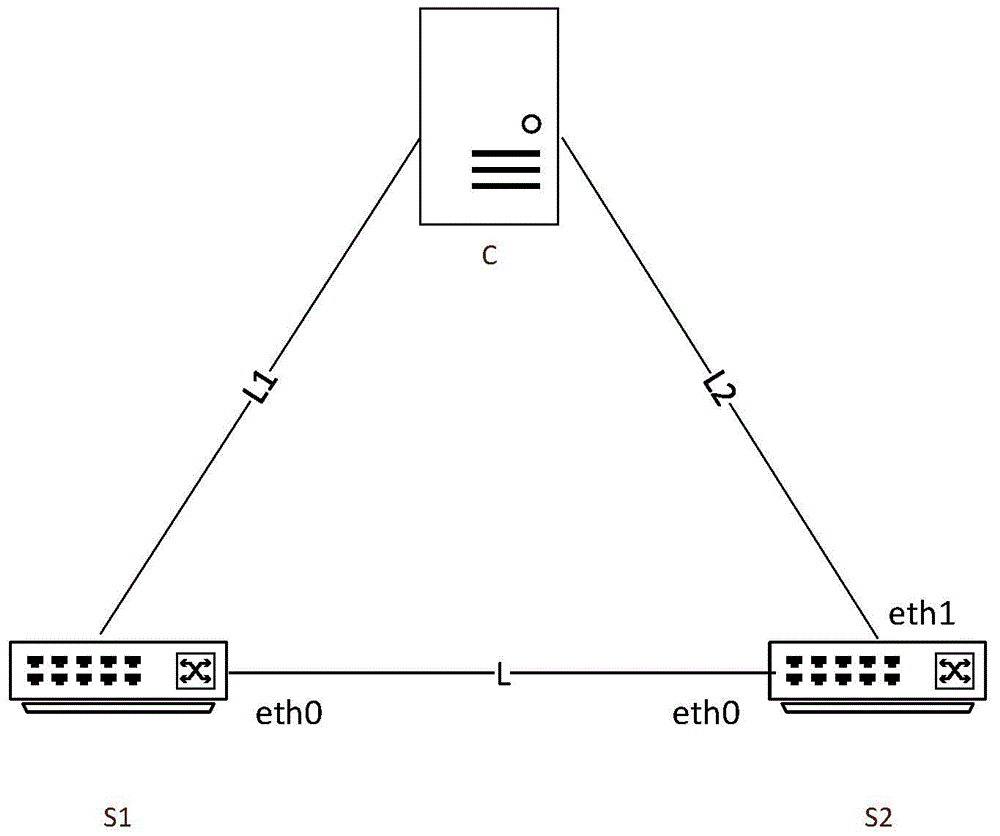
[0029] Step 1: Set up and install an SDN controller C, Openflow switch S1, and Openflow switch S2. The SDN controller can be Floodlight, ryu, OpenDayLight and other controller types. The three devices are interconnected with network cables, and the SDN controller C and Openflow are set. The eth0 interface of the switch S1 is interconnected, the SDN controller C is connected to the eth0 interface of the Openflow switch S2, and the eth1 interface of the Openflow switch S1 is connected to the eth1 interface of the Openflow switch S2.

[0030] Among them: SDN: is the abbreviation of Software Defined Network, which is a new type of network innovation architecture, which realizes flexible control of network traffic by separating the control plane of network equipment from the data plane;

[0031] OpenFlow: It is the most widely used among the many protocols for communication bet...

Embodiment 2

[0075] A method for measuring link delay between switches based on software-defined networking, characterized in that:

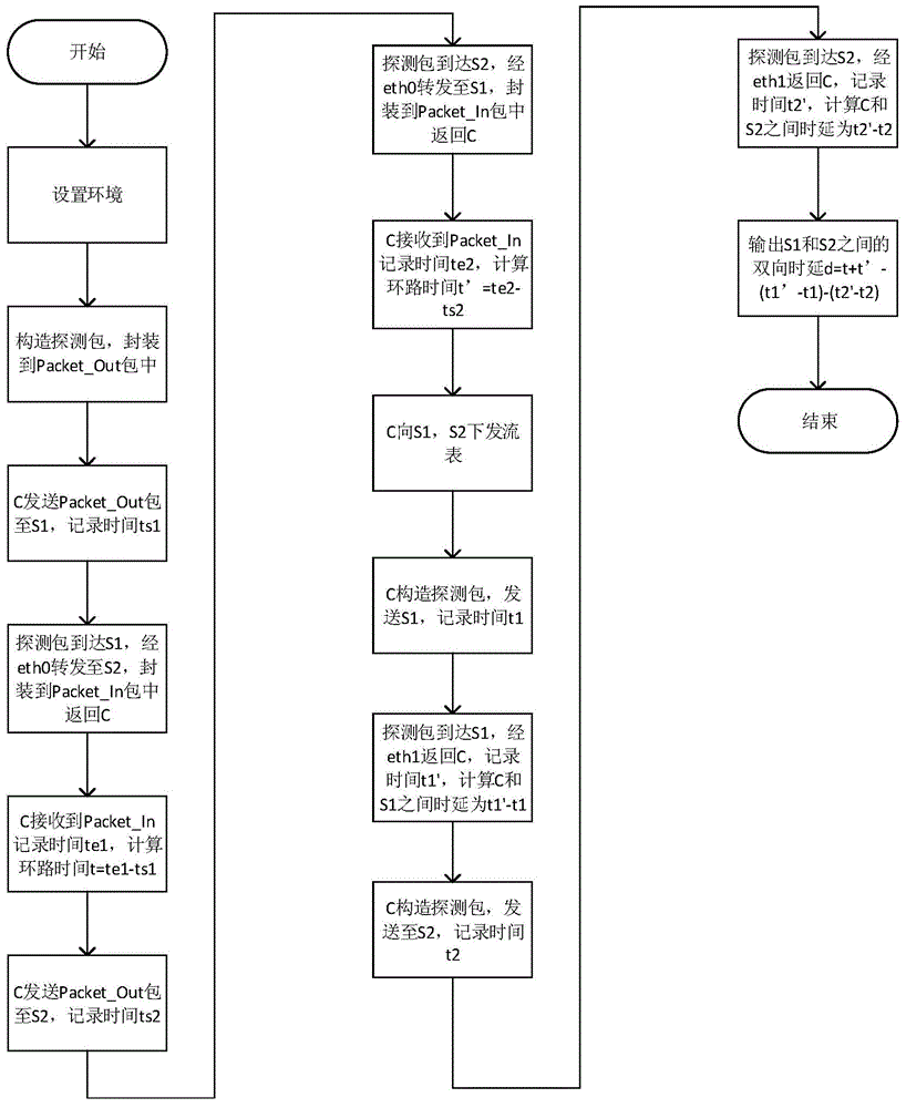
[0076] Step 1: Set up and install an SDN controller C, Openflow switch S1, and Openflow switch S2. The three devices are interconnected using network cables, and the SDN controller C is connected to the eth0 interface of the Openflow switch S1, and the SDN controller C is connected to the Openflow switch. The eth0 interface of S2 is interconnected, and the eth1 interface of the Openflow switch S1 is connected to the eth1 interface of the Openflow switch S2, and then enter step 2;

[0077] Step 2: Controller C constructs a Packet_Out packet, sets the action of the Packet_Out packet as output, sets the out_port of the Packet_Out packet as eth0, and proceeds to step 3;

[0078] Step 3: Controller C sends the constructed Packet_Out packet to Openflow switch S1, and at the same time records the current timestamp of controller C as ts1, ts1=5ms, and enters step 4;...


PUM


Abstract

The invention discloses an inter-switch link time delay measuring method based on a software defined network. The inter-switch link time delay measuring method comprises the following steps: installing an SDN controller C, an Openflow switch S1, and an Openflow switch S2; enabling the controller C to send a constructed Packet_Out packet to S1; when the Packet_Out packet arrives at S1, enabling S1 to analyze data from the Packet_Out packet, and forward the data from an eth0 interface of S1 to S2; enabling S2 to encapsulate the data packet into a Packet_In packet, and transmit back to the controller C; calculating first loop time by the controller C; in a similar way, sending the constructed Packet_Out packet to S2, and calculating second loop time by the controller C; creating a detecting packet by the controller C, sending the detecting packet to S1, forwarding the packet from an eth1 interface of S1, and returning the packet to the controller C, and sending the constructed detecting packet to S1 by the controller, so as to calculate the bidirectional time delay between the controller C and S2, and calculating the bidirectional time delay between S1 and S2.

Description

technical field [0001] This technical design relates to the technical field of network measurement, in particular to a method for measuring link delay between switches based on a software-defined network. Background technique [0002] Software-Defined Network (SDN, Software-Defined Network) is a new type of network architecture. Different from traditional networks, it proposes the idea of ​​separating the control plane and data plane in the network, so that routers and switches in the network only need to be responsible for Forwarding, without making relevant routing decisions and path learning. In the SDN network, a centralized controller is responsible for overall control and management, and controls the flow of data by issuing a flow table to each node. Most of the delay measurement in the traditional network is end-to-end measurement, and most of them use statistics and estimation strategies, which lack real-time performance and accuracy. Since the network structure of ...

Claims


Application Information

Patent Timeline
Patent Type & Authority Applications(China)
IPC IPC(8): H04L12/26
Inventor 程光胡一非王玉祥吴桦
Owner SOUTHEAST UNIV
Learn More