patient transfer bed

A transfer bed and patient technology, applied in the field of patient transfer bed, can solve the problems of increased patient pain, high labor intensity, poor lifting safety, etc., and achieve the effect of convenient use, strong practicability, stable and safe transfer

Inactive Publication Date: 2017-05-17
ANHUI CHENRUI ENERGY CONSERVATION & ENVIRONMENTAL PROTECTION SCI & ENG
View PDF11 Cites 0 Cited by
  • Summary
  • Abstract
  • Description
  • Claims
  • Application Information

AI Technical Summary

Problems solved by technology

[0002] After the operation, the patient’s body is extremely weak, the pain is unbearable, and the movement of the limbs is inconvenient. In this case, it is necessary to use the transfer bed to transport the patient back to the hospital bed. Since most of the existing transfer beds do not have lifting devices, more than two nurses are often needed It can only be completed with the assistance of personnel and family members. This is not only labor-intensive, but often due to unskilled operation, it increases the pain of the patient, is not conducive to postoperative recovery, and may cause unexpected serious consequences.
In the prior art, there are also a small number of transfer beds equipped with a sling-type lifting device or a shovel-type lifting device, but the above-mentioned lifting devices all have certain defects. The sling-type is easy to shake after lifting, and the lifting safety is poor. and other shortcomings; so at this stage, there is an urgent need for a transport device that can smoothly transport patients after surgery without causing pain to the patient. After extensive searching, no ideal technical solution has been found yet.

Method used


Image

  • patient transfer bed
  • patient transfer bed
  • patient transfer bed

Examples


Embodiment 1

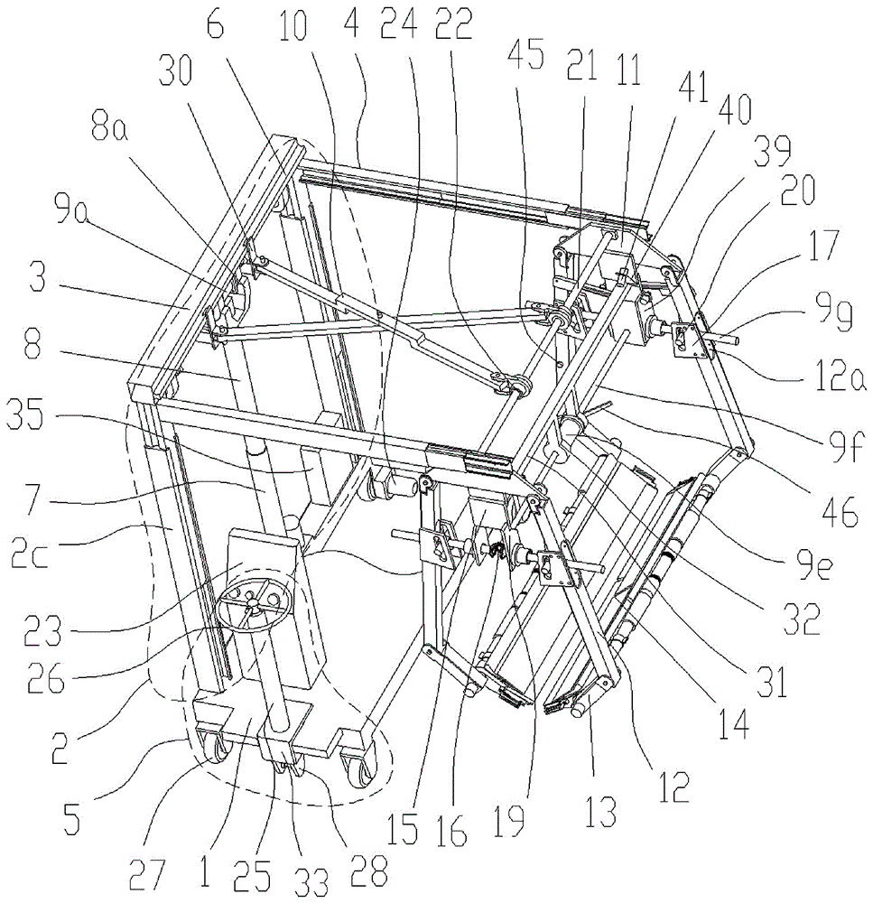
[0029] Embodiment 1: as figure 1 As shown, a patient transfer bed provided by the present invention is characterized in that it includes a base 1, the base 1 is a U-shaped frame, and a layer of baffles is wrapped on the U-shaped frame, and four under the base 1 Corners are respectively connected with a wheel 27, and the two wheels 27 on the rear side are universal wheels, and the two on the front side are generally wheels that cannot change direction at will.

[0030] combine Figure 5 As shown, a crossbeam 3 is supported and fixed on the base 1 by a support device 2, and a transverse slide rail 4 is respectively fixedly connected to both sides of the crossbeam 3. The support device 2 includes two 1 longitudinal slide rails 2c on both sides, one end of the slide rail seat of the longitudinal slide rail 2c is welded on the base 1, and the upper ends of the slide plates of the two longitudinal slide rails 2c are respectively welded to the bottoms of the two ends of the beam 3. ...

Embodiment 2

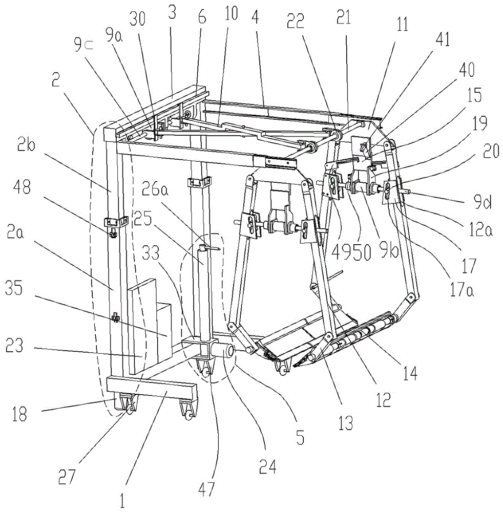
[0039] Embodiment 2: as figure 2 and Figure 6 As shown, in Embodiment 1, the support device 2 can also have the following structure, which includes a guide tube 2a connected to the base 1, a support rod 2b is movably connected to the guide tube 2a, and the A servo motor 8 is provided at the bottom of the guide tube 2a, and the output shaft of the servo motor 8 is supported and matched with the support rod 2b through a screw and a screw nut.

[0040] The guide tube 2a and the support rod 2b are square structures, and a guide device is provided on the upper end of the guide tube 2a, and the guide device includes four U-shaped seats 2d respectively arranged at corresponding corners of the guide tube 2a. Each U-shaped seat 2d is connected to a freely rotatable guide wheel 2f through a fixed shaft 2g, and the guide wheel 2f is guided and matched with the corresponding edge of the support rod 2b.

Embodiment 3

[0041] Embodiment 3: In embodiment 1, the steering device 5 can also be the following structure, which includes a U-shaped connecting seat 33 fixedly connected to the base 1, and a fixed pipe 25 is welded on the U-shaped connecting seat 33. The fixed pipe 25 is rotated and connected to a rotating shaft. The upper end of the rotating shaft is connected to a direction handle 26a, and the lower end is connected to one of the wheels 27 on the lower side of the base 1. A drive motor 24 is also connected to the wheel 27. The drive motor 24 The control cabinet 23 is connected by wires and powered by the mobile power supply 35 .


PUM


Abstract

The invention relates to a patient transfer bed which is characterized by comprising a base (1), wherein a fixed cross beam (3) is supported on the base through a supporting device (2); transverse slide rails (4) and a first bidirectional motor (9a) are connected to the cross beam respectively; first lead screws (9c) are connected to two output shafts of the first bidirectional motor; a transverse connecting rod (10) is crossly hinged to each first lead screw through a screw nut (30); the two transverse connecting rods are connected with a longitudinal connecting rod (21); two swing rods (12) are hinged to a slide plate of each transverse slide rail through a connecting plate(11); shovel plates (14) are connected to the swing rods on the same sides of the two connecting plates; the two shovel plates are correspondingly matched; an opening and closing device for controlling the opening and closing movement of the swing rods is arranged between the two swing rods. The patient transfer bed has the advantages that the use is convenient, various patients can be transferred, the transfer is stable and safe, the carrying process is stable, and the pain of the patients during carrying can be effectively relieved.

Description

technical field [0001] The invention relates to a patient transporting device, in particular to a patient transfer bed. Background technique [0002] After the operation, the patient’s body is extremely weak, the pain is unbearable, and the movement of the limbs is inconvenient. In this case, it is necessary to use the transfer bed to transport the patient back to the hospital bed. Since most of the existing transfer beds do not have lifting devices, more than two nurses are often needed It can only be completed with the assistance of personnel and family members, which is not only labor-intensive, but also often increases the pain of the patient due to unskilled operation, is not conducive to postoperative recovery, and may cause unexpected serious consequences. In the prior art, there are also a small number of transfer beds equipped with a sling-type lifting device or a shovel-type lifting device, but the above-mentioned lifting devices all have certain defects. The sling...

Claims


Application Information

Patent Timeline
Patent Type & Authority Patents(China)
IPC IPC(8): A61G7/14
Inventor 叶强宋锐
Owner ANHUI CHENRUI ENERGY CONSERVATION & ENVIRONMENTAL PROTECTION SCI & ENG
Why Eureka
Try Eureka