A bottom cold end spraying equipment

A technology of spraying equipment and cold end, which is applied in the direction of coating, spray booth, spraying device, etc. It can solve the problems of spraying dead angle, incomplete protective film, and asynchronous distance adjustment, etc., to achieve cost saving, uniform spraying without dead angle, and increase smoothness The effect of degree and wear resistance

Active Publication Date: 2016-11-30
QINGDAO YUTAI PHARMA PACKAGING TECH CO LTD
View PDF5 Cites 0 Cited by
  • Summary
  • Abstract
  • Description
  • Claims
  • Application Information

AI Technical Summary

Problems solved by technology

[0003] The technical problem to be solved by the present invention is: the spraying effect of the existing equipment is limited by the number of nozzles and the sliding speed of the sliding carriage block, which cannot flexibly adapt to the running speed of the mesh belt of the annealing furnace, the angle of the sliding carriage cannot be adjusted, and the annealing mesh belt cannot be adjusted. When the glass products are arranged unevenly or at different heights, the distance adjustment between the parts on the spraying machine and the glass products is not synchronized, and the spray gun is not running smoothly, which makes the spraying liquid spray unevenly and causes spraying dead ends. The root of the glass products, especially the glass products and The bottom of the mesh belt contact cannot be sprayed, and the nozzle is easy to spray the spray liquid into the interior of the glass product, especially when producing large-diameter glass products such as jars and glass dishes, it is very easy to spray the spray liquid into the interior of the glass product. High-pressure atomizing nozzles require a lot of air pressure. Insufficient air pressure of the equipment nozzles will result in insufficient atomization angle area. When the spray volume is large, oily spots or tear marks will appear on the bottle body due to the uneven size of the atomized droplets, which will affect the beauty of the bottle body; When the spray volume is small, it cannot be sprayed to the root of the bottle, and the protective film is incomplete

Method used


Image

  • A bottom cold end spraying equipment
  • A bottom cold end spraying equipment
  • A bottom cold end spraying equipment

Examples


Embodiment 1

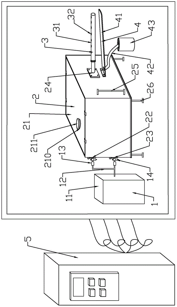
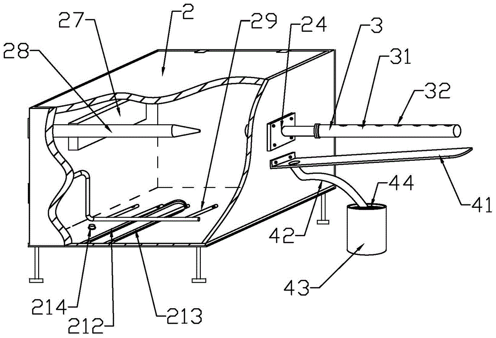
[0032] A bottom cold end spraying equipment, comprising an air supply system 1, an atomization system 2, a mist output system 3 and a material saving recovery system 4; the atomization system includes a tank body 21, a bracket 26, a temperature control heating device 212, a bottom Spray device 29, upper end diversion spray gun 28, described temperature control heating device 212, bottom spray device 29, upper end diversion spray gun 28 are all arranged in the inside of tank body 21; Described tank body 21 is a sealed tank body, tank body 21 The top is provided with a feeding port 210 for adding spraying liquid, an upper air inlet 22, a lower air inlet 23, a mist discharge port 24 and a liquid level gauge 25; the feeding port 210 is provided with a sealing cover 211, and the upper end guide The flow spray gun 28 is connected to the air supply system 1 through the upper air inlet 22, the air supply system 1 is located outside the tank body 21, the spray direction of the nozzle of...

Embodiment 2

[0038] A bottom cold end spraying equipment, comprising an air supply system 1, an atomization system 2, a mist output system 3 and a material saving recovery system 4; the atomization system includes a tank body 21, a bracket 26, a temperature control heating device 212, a bottom Spray device 29, upper end diversion spray gun 28, described temperature control heating device 212, bottom spray device 29, upper end diversion spray gun 28 are all arranged in the inside of tank body 21; Described tank body 21 is a sealed tank body, tank body 21 The top is provided with a feeding port 210 for adding spraying liquid, an upper air inlet 22, a lower air inlet 23, a mist discharge port 24 and a liquid level gauge 25; the feeding port 210 is provided with a sealing cover 211, and the upper end guide The flow spray gun 28 is connected to the air supply system 1 through the upper air inlet 22, the air supply system 1 is located outside the tank body 21, the spray direction of the nozzle of...

Embodiment 3

[0045] A bottom cold end spraying equipment, comprising an air supply system 1, an atomization system 2, a mist output system 3 and a material saving recovery system 4; the atomization system includes a tank body 21, a bracket 26, a temperature control heating device 212, a bottom Spray device 29, upper end diversion spray gun 28, described temperature control heating device 212, bottom spray device 29, upper end diversion spray gun 28 are all arranged in the inside of tank body 21; Described tank body 21 is a sealed tank body, tank body 21 The top is provided with a feeding port 210 for adding spraying liquid, an upper air inlet 22, a lower air inlet 23, a mist discharge port 24 and a liquid level gauge 25; the feeding port 210 is provided with a sealing cover 211, and the upper end guide The flow spray gun 28 is connected to the air supply system 1 through the upper air inlet 22, the air supply system 1 is located outside the tank body 21, the spray direction of the nozzle of...


PUM


Abstract

The invention provides a bottom cold-end spraying device. The bottom cold-end spraying device comprises an air supply system, an atomizing system, a mist output system and a material-saving recovering system; the atomizing system comprises a tank body, a temperature control heating device, a bottom mist spray device and an upper end flow guide spray gun; the tank body is equipped with a feeding opening for feeding spraying liquid, an upper end air inlet, a lower end air inlet, a mist outlet and a level indicator; the upper end flow guide spray gun is connected with the air supply system through the upper end air inlet; a nozzle of the upper end flow guide spray gun directly faces the mist outlet; the mist outlet is formed in the upper middle part of the sidewall of the tank body and is connected with the mist output system at the outer part of the tank body; the material-saving recovering system is arranged below the mist output system; the bottom mist spray device is connected with the air supply system through the lower end air inlet; the bottom mist spray device and the temperature control heating device are arranged in the tank body, close to the bottom part. When in use, the device directly sprays from the bottom part of a bottle body. The device has the advantages that the shortages in the existing cold-end spraying technology can be overcome; the dead corner in spraying is avoided; the operation is simple and convenient; the spraying liquid is saved.

Description

technical field [0001] The invention relates to a cold end spraying equipment required in the glass product processing process, in particular to a bottom cold end spraying equipment. Background technique [0002] Cold-end spraying equipment refers to the equipment that sprays an organic protective layer on the surface of glass products after the glass products are cooled in an annealing furnace. There are many deficiencies in the cold end spraying equipment currently used. Existing cold-end spraying machine adopts the top of the annealing furnace mesh belt, and the nozzle on the fixed and sliding bracket travels back and forth to spray the spraying liquid on the top of each row of glass products on the annealing furnace mesh belt for spraying. The spraying effect of this kind of equipment is limited by the number of nozzles and the sliding speed of the sliding bracket pulley. It cannot flexibly adapt to the running speed of the mesh belt of the annealing furnace, the angle ...

Claims


Application Information

Patent Timeline
Patent Type & Authority Patents(China)
IPC IPC(8): B05B15/12B05B9/03B05B15/04B05B15/00
CPCB05B9/03B05B14/00B05B15/00B05B16/00
Inventor 李伟林
Owner QINGDAO YUTAI PHARMA PACKAGING TECH CO LTD
Why Eureka
Try Eureka