Supercharge Your Innovation With Domain-Expert AI Agents!

Stamping device used for forming spike heads

A punching device and head technology, which is applied in the field of punching devices for forming the head of a spike, can solve the problems of high punching force, damage to the head of the spike, and low quality of the forming of the spike, so as to improve the quality of the spike. Effect

Inactive Publication Date: 2015-04-08
CHONGQING HUARUI STANDARD COMPONENT MFG CO LTD
View PDF0 Cites 1 Cited by
  • Summary
  • Abstract
  • Description
  • Claims
  • Application Information

AI Technical Summary

Problems solved by technology

The existing stamping device used for the head of the road stud generally uses the piston rod of the cylinder to drive the punch to punch directly, and the punching force is relatively high at one time. After stamping, the head of the road stud often has defects such as damage, cracks or scars. Low quality of part molding

Method used


Image

  • Stamping device used for forming spike heads

Examples


Embodiment Construction

[0012] Below in conjunction with accompanying drawing and specific embodiment the present invention will be described in further detail:

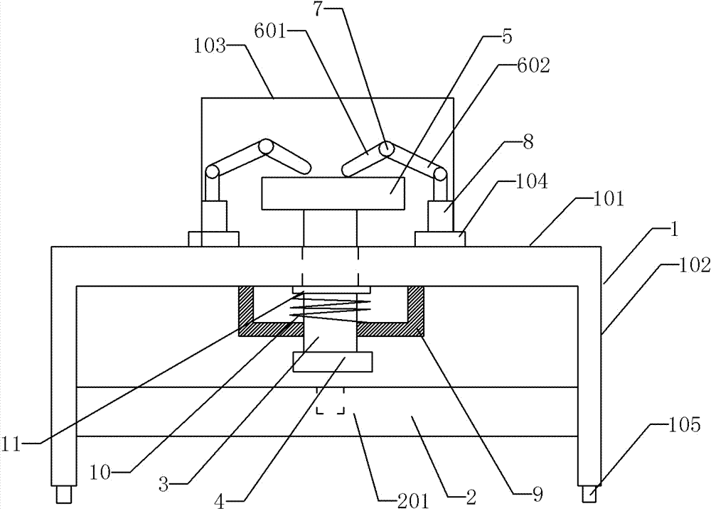
[0013] Such as figure 1 The stamping device shown for forming the head of the spike includes a base 1, a support table 101, a foot 102, a boss 103, a bearing table 104, a universal wheel 105, a stamping table 2, a positioning groove 201, a stamping rod 3, Punch 4, end plate 5, V-shaped rod driven end 601, V-shaped rod driven end 602, two pin shafts 7, two cylinders 8, spring mounting seat 9, return spring 10 and gasket 11.

[0014] The base 1 includes a horizontal supporting platform 101 and two legs 102 arranged on both sides of the supporting platform, four universal wheels 105 are arranged symmetrically under the two supporting feet 102, the boss 103 is arranged on the upper part of the supporting platform 101, and is located at The supporting platform 101 is centered, and the carrying platform 104 is symmetrically arranged on both side...


PUM


Abstract

The invention provides a stamping device used for forming spike heads. The stamping device comprises a base provided with a supporting table face and two supporting legs. The supporting legs are arranged on two sides of the supporting table face horizontally arranged. A horizontal stamping table surface is fixed between the supporting legs. A vertical positioning groove is formed in the middle of the upper surface of the stamping table face. A guide hole is formed in the supporting table face and corresponds to the positioning groove. A stamping rod penetrates the guide hole. The lower end of the stamping rod is provided with a stamping head, and the upper end of the stamping rod extends out of the guide hole to be fixed with an end plate. Two V-shaped connecting rods and a boss which is arranged on the stamping table face are further provided. The V-shaped connecting rods are symmetrically arranged relative to a center axis of the stamping rod. Driven ends of the V-shaped connecting rods are all abutted against the end plate. The V-shaped connecting rods are hinged with pins at V-shaped corners. The pins are symmetrically arranged on the boss. Driving ends of the V-shaped connecting rods are hinged to piston rods of two cylinders.

Description

technical field [0001] The invention relates to stamping technology, in particular to a stamping device for forming the head of a spike. Background technique [0002] Spikes are divided into railway spikes and road spikes. Railway spikes have a flat head and are usually formed by cold heading or stamping. The existing stamping device used for the head of the road stud generally uses the piston rod of the cylinder to drive the punch to punch directly, and the punching force is relatively high at one time. After stamping, the head of the road stud often has defects such as damage, cracks or scars. The quality of part molding is low. Contents of the invention [0003] The invention provides a stamping device capable of improving the forming quality of the spike head. [0004] The present invention scheme is as follows: [0005] A stamping device for forming the head of a spike, including a base, the base includes a horizontal support platform and two legs arranged on bot...

Claims


Application Information

Patent Timeline
Patent Type & Authority Applications(China)
IPC IPC(8): B21G3/12
Inventor 蔡良华
Owner CHONGQING HUARUI STANDARD COMPONENT MFG CO LTD
Features
  • R&D
  • Intellectual Property
  • Life Sciences
  • Materials
  • Tech Scout
  • Unparalleled Data Quality
  • Higher Quality Content
  • 60% Fewer Hallucinations
Learn More