Automatic centering fixture for annular workpieces

An automatic centering, annular workpiece technology, applied in the direction of manufacturing tools, metal processing mechanical parts, clamping, etc., can solve the problem that the arc side of the annular workpiece cannot be well positioned, it is not easy to process the outer circle of the pipe fittings, and the wall thickness of the pipe fittings is not easy to be processed. Uniformity and other issues, to save production time, increase stability, facilitate accurate positioning and clamping

Inactive Publication Date: 2015-04-08
CHONGQING QUANHAI MACHINERY
View PDF0 Cites 8 Cited by
  • Summary
  • Abstract
  • Description
  • Claims
  • Application Information

AI Technical Summary

Problems solved by technology

However, this method often makes the wall thickness of the pipe fittings uneven
[0003] A centering fixture commonly used now includes a bracket, a motor, a first feed screw connected to the motor through a second coupling, a second feed screw parallel to the first feed screw, and a second feed screw connected to the first feed screw. The first coupling and guide plate in the center of the feed screw, because the guide plate is a plane structure, directly center and compress the ring workpiece, and the arc side of the ring workpiece cannot be well positioned and easy to slip, and because it is from the ring workpiece If the outside is pressed and centered, it is not easy to process the outer circle of the pipe fitting

Method used


Image

  • Automatic centering fixture for annular workpieces

Examples


Embodiment Construction

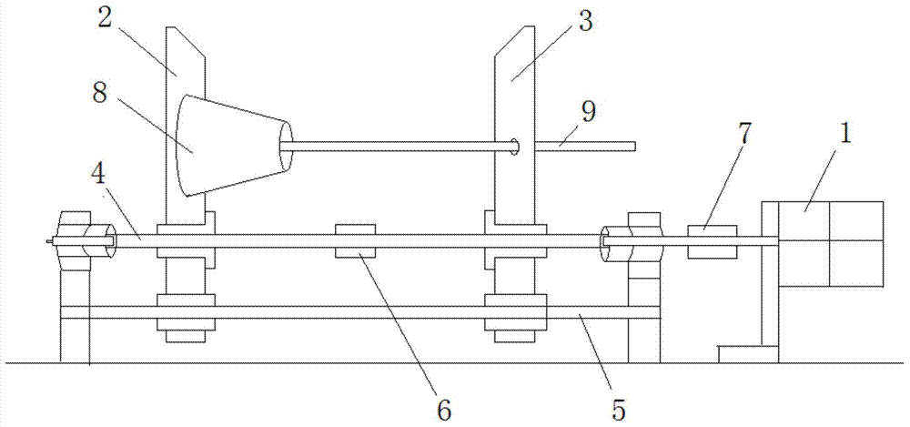
[0014] The present invention will be further described below in conjunction with the accompanying drawings and examples, but not as a limitation to the present invention.

[0015] Such as figure 1 As shown, a self-centering fixture for a circular workpiece includes a bracket, a motor 1 screwed to the bracket, a first feed screw 4 screwed to the bracket through a second coupling 7, and the first feed screw 4. The second feed screw 5 parallel to the feed screw 4 is screwed to the first coupling 6 at the left and right ends of the first feed screw 4, and also includes a first guide plate 2 and a second guide plate 3; the first guide plate 2 and The lower end of the second guide plate 3 is respectively welded with two sliding seats, and the two sliding seats are respectively threaded with the first feed screw 4 and the second feed screw 5, and the first guide plate 2 is welded with a tapered tubular mandrel 8 and a long rod-shaped positioning post 9, the mandrel 8 is large on the...


PUM


Abstract

The invention discloses an automatic centering fixture for annular workpieces. The automatic centering fixture comprises a support, a motor, a first feed lead screw, a second feed lead screw, a first coupling, a first guide plate and a second guide plate. The motor is fixedly connected with the support, the first feed lead screw is connected with the support by a second coupling, the second feed lead screw is parallel to the first feed lead screw, and the first coupling is connected with the left end and the right end of the first feed lead screw; two slide seats are respectively welded at the lower end of the first guide plate and the lower end of the second guide plate and are respectively connected with the first feed lead screw and the second feed lead screw, a conical tubular mandrel and a positioning column in the shape of a long rod are arranged on the first guide plate, the left portion of the mandrel is large while the right portion of the mandrel is small, and the positioning column is positioned in the center of the mandrel; a circular hole is formed in the second guide plate, and the positioning column penetrates the circular hole and is parallel to the first feed lead screw. The automatic centering fixture has the advantages that the production time can be effectively saved, the movement stability can be improved, and the automatic centering fixture brings convenience for accurately positioning and clamping the annular workpieces.

Description

technical field [0001] The invention relates to a fixture, in particular to an automatic centering fixture for a circular workpiece. Background technique [0002] In mechanical processing, some workpieces need to be positioned and clamped through their inner holes, especially when processing the outer circle and end face of annular pipe fittings. In the past, when processing ring-shaped pipe fittings, one end was often stuck and the other end was pressed for processing, and the end that was held up had to be matched with a wooden plug or a wooden block in the inner hole according to the inner hole of the pipe fitting. Only then can it be processed tightly with the top. However, this method often makes the wall thickness of the pipe fittings uneven. [0003] A centering fixture commonly used now includes a bracket, a motor, a first feed screw connected to the motor through a second coupling, a second feed screw parallel to the first feed screw, and a second feed screw conne...

Claims


Application Information

Patent Timeline
Patent Type & Authority Applications(China)
IPC IPC(8): B23Q3/00
CPCB23Q3/00B23Q2703/10
Inventor 张水泉
Owner CHONGQING QUANHAI MACHINERY
Why Eureka
Try Eureka