a wind-driven flagpole

A flagpole and wind-driven technology, applied in the field of wind-driven flagpoles, can solve the problem that the flag cannot flutter with the wind

Inactive Publication Date: 2017-10-03
贺先文
View PDF8 Cites 0 Cited by
  • Summary
  • Abstract
  • Description
  • Claims
  • Application Information

AI Technical Summary

Problems solved by technology

[0004] The purpose of the present invention is to overcome the problem that the existing flagpole cannot fly with the wind when the wind is small or the wind direction is wrong

Method used


Image

  • a wind-driven flagpole
  • a wind-driven flagpole
  • a wind-driven flagpole

Examples


Embodiment 1

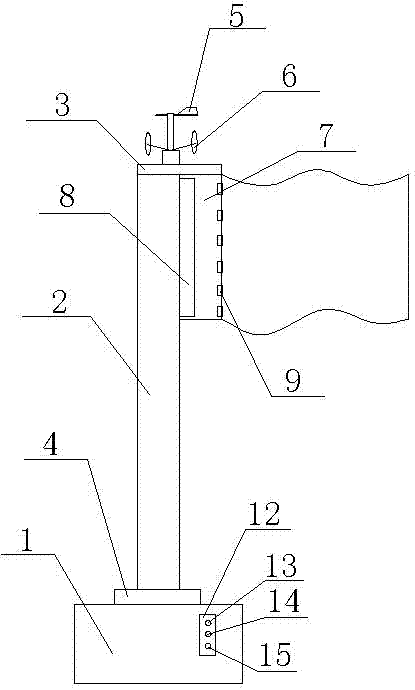
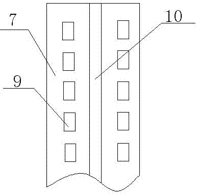
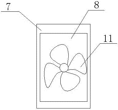
[0017] In order to overcome the problem that the traditional flagpole has no detection function of wind direction and wind speed, and cannot control the direction and extent of flag spreading, the present invention provides a figure 1 , figure 2 and image 3 The wind-operated flagpole shown includes a flagpole seat 1, a flagpole 2 and a flag fixing device 7 slidingly connected with the flagpole 2. A top plate 3 is provided on the top of the flagpole 2, and a wind vane 5 and an anemometer are fixedly connected to the top plate 3. 6. An electric turntable 4 is fixedly connected between the flagpole seat 1 and the flagpole 2. The flag fixing device 7 is a hollow structure, and a fan placement slot 8 is arranged inside the fan placement slot 8, and a fan 11 is fixedly connected in the fan placement slot 8. , the center of the upper surface of the flag fixing device 7 is longitudinally provided with a flag fixing groove 10, and the two sides of the flag fixing groove 10 are provi...

Embodiment 2

[0021] On the basis of Embodiment 1, the flagpole 2 is a hollow structure, and the power cord connecting the anemometer 6 and the fan 11 is arranged in the flagpole 2 to avoid damage to the power cord; one side of the top plate 3 extends out of the flagpole 2, and The flag-fixing side edges of the flag-fixing device 7 are aligned to prevent the flag-fixing device from being pulled up excessively.

[0022] In addition, the external power supply of the flagpole for supplying power to the anemometer 6, the fan 11 and the electric turntable 4 is a solar cell, the solar cell is installed on the flagpole 2, and the flagpole is generally placed outdoors, which can make full use of solar energy, save resources and save costs. And in order to avoid the blower switch 13 on the control panel 12, the electric turntable switch 14 and the anemometer switch 15 from being damaged, described control panel 12 is provided with waterproof cover.


PUM


Abstract

The invention provides a flagpole capable of achieving a flutter with the wind. The flagpole comprises a flagpole base, a flagpole and a flag fixing device in sliding connection with the flagpole, wherein a top plate is arranged at the top of the flagpole; the top plate is fixedly connected with a wind vane and an anemoscope; an electric rotating disc is fixedly connected between the flagpole base and the flagpole; the flag fixing device has a hollow structure; a blower accommodating groove is formed in the flag fixing device; a blower is fixedly connected into the blower accommodating groove; a flag fixing groove is arranged lengthways in the center of the upper surface of the flag fixing device; a plurality of wind outlet holes arranged lengthways at equal intervals are formed in two sides of the flag fixing groove; a control panel is arranged on the flagpole base; a blower switch, an electric rotating disc switch and an anemoscope switch are arranged on the control panel; and the blower, the electric rotating disc and the anemoscope are connected with an external flagpole power supply through the blower switch, the electric rotating disc switch and the anemoscope switch, respectively. The flagpole capable of achieving a flutter with the wind can adjust the direction of a flag to enable the flag to stay in a windward state; and the blower is fixed in the flag fixing device, so that the flag can flutter in the whole lifting process without wasting energy.

Description

technical field [0001] The invention relates to a wind operated flagpole. Background technique [0002] At present, if the wind is not strong or the direction of the wind is wrong, the flag will not flutter with the wind in many occasions, and the purpose of flag raising and fluttering will be lost, which will cause regret for people! There is generally no wind speed detection device on the existing blowing flagpoles, so people can only judge whether they need to open the blowing device through sensory experience, which will cause the flag to not be spread or waste the energy sent by the blowing device. [0003] In addition, the traditional flagpole is generally fixed on the flagpole base, and the flag is also fixed on one side of the flagpole. When the wind direction of the natural wind is inconsistent with the direction in which the flag is flying, the flag will wrap around the pole and cannot be spread out, which will affect the appearance. . Contents of the invention ...

Claims


Application Information

Patent Timeline
Patent Type & Authority Patents(China)
IPC IPC(8): E04H12/32
CPCE04H12/32
Inventor 贺先文
Owner 贺先文
Why Eureka
Try Eureka