Voltage averaged allocator for charging and discharging lithium battery

A voltage averaging, lithium battery technology, applied in battery circuit devices, current collectors, electric vehicles, etc., can solve problems such as power loss

Active Publication Date: 2009-07-08
哈尔滨光宇电子有限公司
View PDF4 Cites 0 Cited by
  • Summary
  • Abstract
  • Description
  • Claims
  • Application Information

AI Technical Summary

Problems solved by technology

[0003] The present invention provides a lithium battery charging and discharging voltage average divider that does not waste the electric energy of the rechargeable battery, which overcomes the defect that the existing voltage average divider causes additional power loss

Method used


Image

  • Voltage averaged allocator for charging and discharging lithium battery
  • Voltage averaged allocator for charging and discharging lithium battery
  • Voltage averaged allocator for charging and discharging lithium battery

Examples


specific Embodiment approach 1

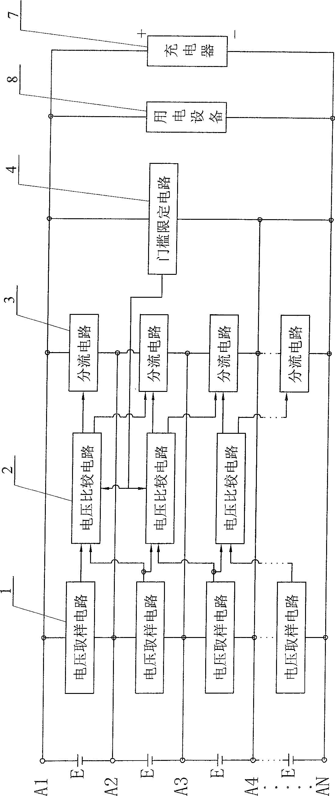
[0005] Specific implementation mode one: the following combination figure 1 This embodiment will be specifically described. In this embodiment, N-1 voltage sampling circuits 1, N-2 voltage comparison circuits 2, N-1 shunt circuits 3, A threshold limiting circuit 4 and N nodes arranged in sequence, the N nodes are sequentially composed of the first node A1, the second node A2 ... and the Nth node AN, and every two adjacent nodes are connected in parallel A voltage sampling circuit 1 and a corresponding shunt circuit 3 are connected; the two input terminals of the voltage comparison circuit 2 are respectively connected to the output terminals of two adjacent voltage sampling circuits 1, and the two outputs of each voltage comparison circuit 2 Each of the two shunt circuits 3 corresponding to the two voltage sampling circuits 1 input to the signal of the voltage comparator circuit 2 is respectively connected to each controlled end of the two adjacent shunt circuits 3, and the t...

specific Embodiment approach 2

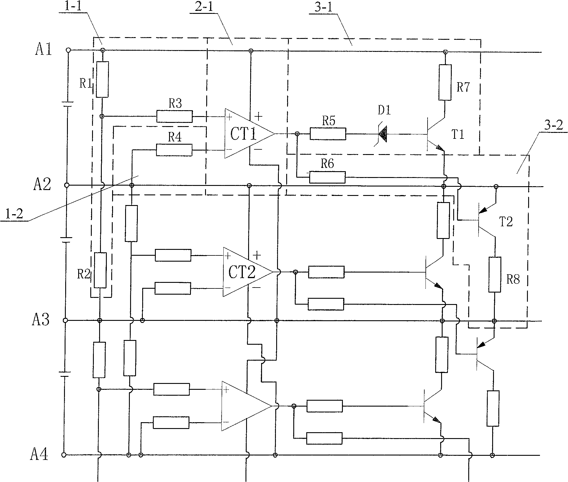
[0006] Specific implementation mode two: the following combination figure 2 This embodiment will be specifically described. The difference between this embodiment and Embodiment 1 is that the No. 1 voltage sampling circuit 1-1 between the first node A1 and the second node A2 is composed of a first resistor R1, a second resistor R2 and a third resistor R3. The second voltage sampling circuit 1-2 between the second node A2 and the third node A3 is composed of the fourth resistor R4, the voltage comparison circuit 2-1 is composed of the first integrated operational amplifier CT1, the first node A1 and the second node A2 The No. 1 shunt circuit 3-1 between is composed of the fifth resistor R5, the seventh resistor R7, the first Zener diode D1 and the first triode T1, and the No. 2 shunt circuit between the second node A2 and the third node A3 The shunt circuit 3-2 is composed of the sixth resistor R6, the eighth resistor R8 and the second transistor T2. One end of the first resi...

specific Embodiment approach 3

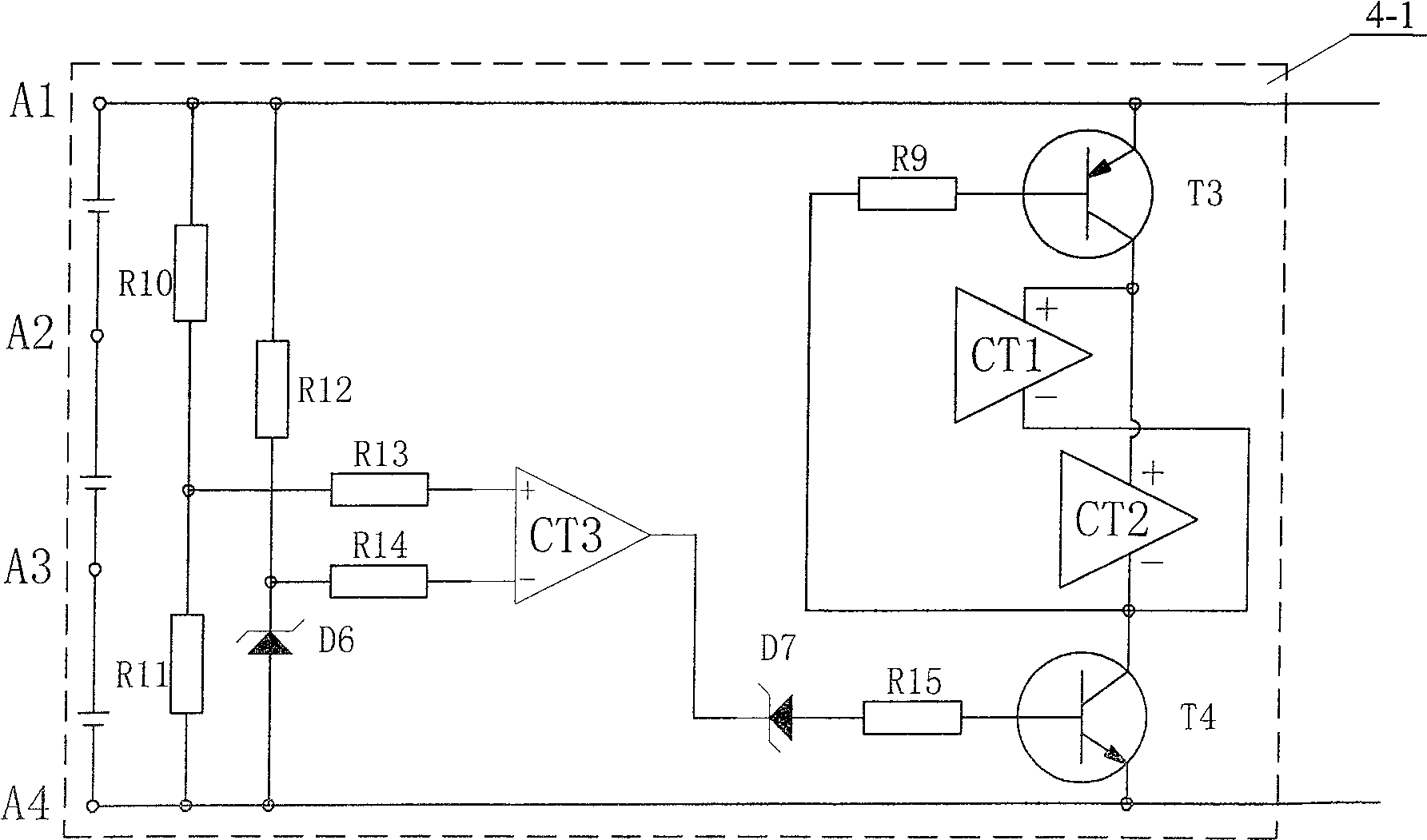
[0007] Specific implementation mode three: the following combination image 3 This embodiment will be specifically described. The difference between this embodiment and the second embodiment is: the threshold limiting circuit 4-1 connected in parallel between the first node A1 and the fourth node A4 is composed of the ninth resistor R9, the tenth resistor R10, the eleventh resistor R11, the Twelfth resistor R12, thirteenth resistor R13, fourteenth resistor R14, fifteenth resistor R15, sixth zener diode D6, seventh zener diode D7, third transistor T3, fourth transistor T4 Composed of the third integrated operational amplifier CT3, the resistance value of the tenth resistor R10 is equal to the resistance value of the eleventh resistor R11, one end of the tenth resistor R10 is connected to the first node A1, one end of the twelfth resistor R12 and the third third The emitter of the pole tube T3, the other end of the tenth resistor R10 is connected to one end of the eleventh resi...


PUM


Abstract

The lithium battery charging and discharging voltage equalizer discloses a voltage protection circuit capable of charging and discharging lithium battery packs connected in series during uninterrupted power supply. It consists of N-1 voltage sampling circuits, N-2 voltage comparison circuits, N-1 shunt circuits, (N-1) / 3 threshold limiting circuits and N nodes arranged in sequence, each adjacent A voltage sampling circuit and a shunt circuit are connected in parallel between the nodes, the two input terminals of the voltage comparison circuit are respectively connected to the output terminals of the two adjacent voltage sampling circuits, and the output terminals of each voltage comparison circuit are respectively connected to the two adjacent shunt circuits. The controlled end of the circuit, the threshold limiting circuit is connected in parallel on the two outermost nodes of the four adjacent nodes, and the output end of each threshold limiting circuit is respectively connected to two controlled terminals of the voltage comparison circuit, and the two voltage comparison circuits are connected to each other. The threshold is defined within the four nodes in which the circuit is connected in parallel. Because there is a threshold limiting circuit, when the lithium battery pack supplies power to electric equipment, the voltage comparison circuit is cut off, so the energy of the lithium battery pack will not be wasted.

Description

Technical field: [0001] The invention relates to a charging and discharging voltage protection circuit for continuous power supply of lithium battery packs connected in series. Background technique: [0002] When charging and discharging lithium batteries, the current and voltage requirements are very strict. Once exceeded, it will have serious consequences in terms of safety and life. Therefore, when lithium batteries are used in series, the parameters of each lithium battery in each group have the same requirements. Due to the cumulative error of each process in the production process of lithium batteries, the parameters of each finished lithium battery will be different, so when used in series, the voltage on each single lithium battery will be different, especially when charging , It is very easy to cause the voltage of a certain lithium battery to exceed the rated value, which will cause irreversible damage and even cause a safety accident in severe cases. The same is ...

Claims


Application Information

Patent Timeline
Patent Type & Authority Patents(China)
IPC IPC(8): H02J7/00
Inventor 顾俊峰李桂森
Owner 哈尔滨光宇电子有限公司
Why Eureka
Try Eureka