A tent pole structure

A pole structure and tent frame technology, which is applied in the field of tents, can solve the problems of increasing manufacturing costs, increasing the weight of the tent frame, and numerous poles, etc., and achieve the effects of increasing service life, reducing manufacturing costs, and reducing repair rates

Inactive Publication Date: 2017-01-04
CAMPVALLEY XIAMEN LEISURE PRODS
View PDF5 Cites 0 Cited by
  • Summary
  • Abstract
  • Description
  • Claims
  • Application Information

AI Technical Summary

Problems solved by technology

[0004] First of all, as a kind of outdoor leisure product, the tent is required to be portable, and the tent with the above structure is supported by multiple sets of rods. There are many rods, and it is difficult and time-consuming to support it. Manufacturing cost, but not light enough when folded
[0005] Secondly, the tent cloth is easy to form pits under the action of gravity, especially when the high-top tent is used in rainy days, the middle position of the tent cloth between the center stem and the side push rod group is more likely to be concave under the impact of rainwater to form water accumulation, which will aggravate The load of the tent frame is also easy to be splashed by accumulated water when the tent is disassembled, which affects the service life of the tent
[0006] Furthermore, since the side push rod group is pivotally connected by at least two rods, after the above-mentioned tent has accumulated water, the force points of the side push rod group will all move to the pivot point of the two rods, that is, the pivot joint must bear the tension of the tent. The weight of the cloth and the accumulated water, so the hinge is very easy to break, which affects the service life of the tent. This is also the part with a high repair rate of the current tent, and it is urgent to improve

Method used


Image

  • A tent pole structure
  • A tent pole structure
  • A tent pole structure

Examples


Embodiment Construction

[0041] In order to further explain the technical solution of the present invention, the present invention will be described in detail below through specific examples.

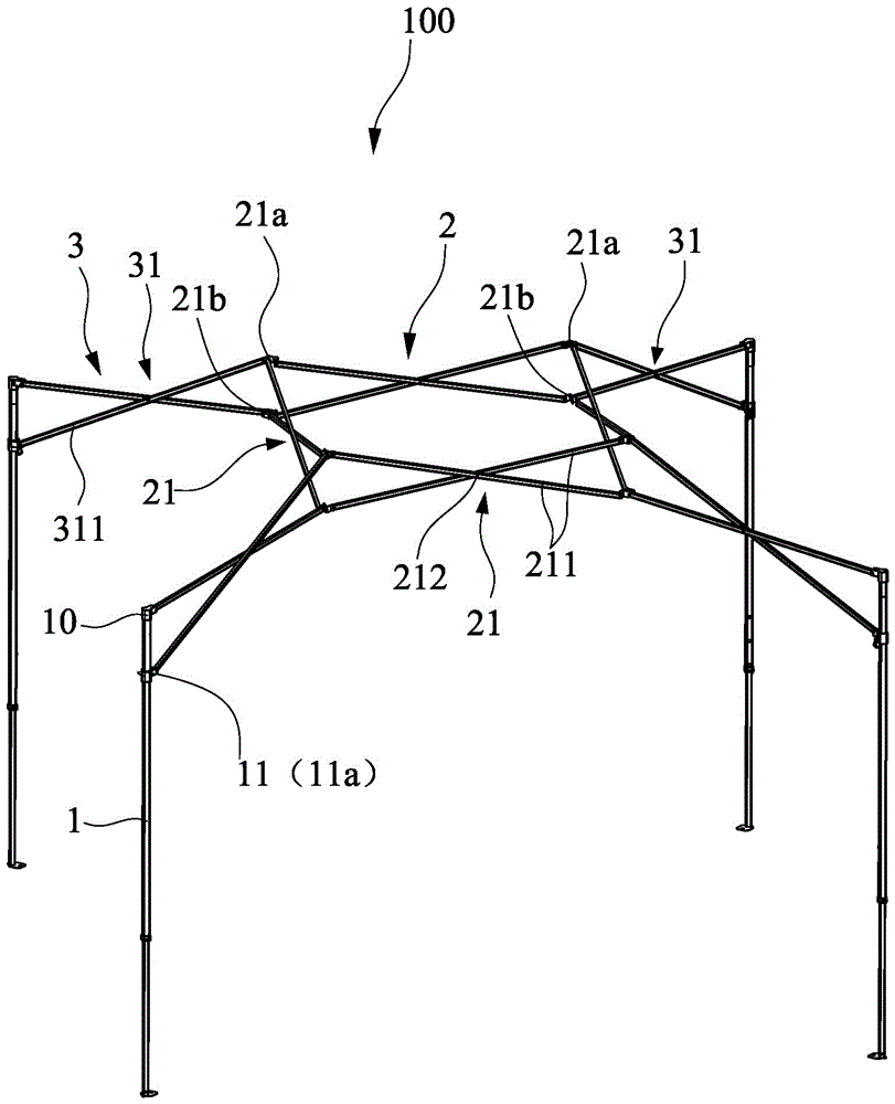
[0042] figure 1 It is the first preferred embodiment of the present invention. As shown in the figure, a tent pole structure 100 of the present invention includes four vertical poles 1, roof brackets 2 and supporting push rod groups 3, vertical poles 1 and roof brackets 2 They all directly contact with the tent cloth (not shown in the figure) and form support for the tent cloth. Of course, the number of poles 1 can also be three, five or more, which can be selected according to actual needs. The pole 1 is a telescopic pole, and the support rod group 3 is used to connect the roof support 2 and the pole 1 .

[0043] Such as figure 1 As shown, the unfolded pole 1 is placed vertically, and of course it can also be arranged to be placed at a predetermined inclination with the ground according to needs. Sliding sl...


PUM


Abstract

The invention discloses a tent hack lever structure, which comprises vertical rods, a tent top bracket and a supporting mandril group, wherein each vertical rod is provided with a permanent seat and a sliding seat; the tent top bracket comprises four groups of connecting rod units, wherein the tails and the heads of the connecting units are mutually hinged and unfolded to form a square, and four groups of hinged points are formed; each group of connecting rod unit comprises two connecting rods, wherein the connecting rods are mutually hinged and unfolded to form an X shape; each group of hinged points respectively form an upper hinged point and a lower hinged point; the supporting mandril group comprises four groups of connecting rod units, wherein each group of connecting rod unit corresponds to one group of hinged points of the tent top bracket; each connecting rod unit of the supporting mandril group comprises two connecting rods which are mutually hinged and form an X shape after being unfolded; two connecting rods, which are connected with the tent top bracket, of each connecting rod unit are hinged to the upper hinged point and the lower hinged point of the tent top bracket; one connecting rod of the connecting rod unit connected with the vertical rods is hinged to a sliding rod, and the other connecting rod is hinged to the permanent seat.

Description

technical field [0001] The invention relates to a tent, in particular to a tent pole structure. Background technique [0002] Existing tent pole structure comprises four upright poles and canopy support, and upright pole is telescopic pole, and upright pole and canopy support all directly contact with tent cloth and form support to tent cloth, between canopy support and every upright pole Both are connected with a set of supporting push rods, and a set of side push rods is connected between every two adjacent vertical rods, and an oblique strut is also connected between each vertical rod and each set of side push rod groups connected to the vertical rod Because the tents are all used outdoors, their structure must be easy to fold and carry. Therefore, the side push rod group connecting the top of the two upright rods of the tent includes at least two rod members and pivot joints that are pivotally connected to each other. [0003] Above-mentioned existing tent has following...

Claims


Application Information

Patent Timeline
Patent Type & Authority Patents(China)
IPC IPC(8): E04H15/46
CPCE04H15/48E04H15/50
Inventor 崔宽峻
Owner CAMPVALLEY XIAMEN LEISURE PRODS
Why Eureka
Try Eureka