Clamping device for fixing

A technology of clamping device and fixing plate, which is applied in the direction of drilling equipment, earthwork drilling, drill pipe, etc., can solve the problems of inconvenient operation, easy slipping of clamping, etc., and achieve the effect of avoiding falling off and improving stability

Active Publication Date: 2015-04-08
CHENGDU ZHIRONG ZHICHUANG INTPROP MANAGEMENT CO LTD
View PDF7 Cites 10 Cited by
  • Summary
  • Abstract
  • Description
  • Claims
  • Application Information

AI Technical Summary

Problems solved by technology

[0003] The technical problem to be solved by the present invention is to provide a clamping device for fixing, so as to overcome the problems of inconvenient operation and easy slipping of clamping when the existing fixing device fixes the drill pipe

Method used


Image

  • Clamping device for fixing
  • Clamping device for fixing
  • Clamping device for fixing

Examples


Embodiment 1

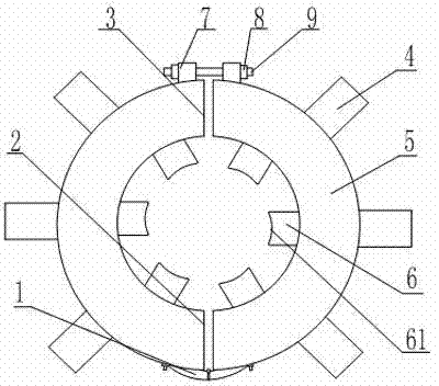
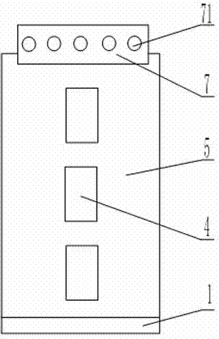
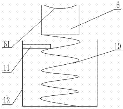
[0021] like Figure 1 to Figure 3 As shown, a clamping device for fixing includes a snap ring body, the outer wall of the snap ring body is provided with a fixed block 4, the snap ring body includes two symmetrically arranged snap rings 5, and the snap ring 5 is provided with an opening 3, a closed End 2, the closed ends of the two snap rings 5 ​​are provided with a loose-leaf 1, and the openings 3 of the two snap rings 5 ​​are welded with a fixed plate 7 cooperating with the screw rod 9 and the nut 8, and the fixed plate 7 is provided with several threaded through holes 71, 6 grooves 12 are provided in the clasp 5, and a reset mechanism 10 is arranged in the groove 12. The reset mechanism 10 is a spring, and a baffle plate 11 is arranged on the inner wall of the groove 12, and a clamping block 6 is arranged on the upper end of the spring. A clamping surface 61 is provided on the block 6, and the clamping surface 61 is recessed inward to form an arc surface, and the arc of the...

Embodiment 2

[0023] like figure 1 , figure 2 , Figure 4 As shown, a clamping device for fixing includes a snap ring body, the outer wall of the snap ring body is provided with a fixed block 4, the snap ring body includes two symmetrically arranged snap rings 5, and the snap ring 5 is provided with an opening 3, a closed End 2, the closed ends of the two snap rings 5 ​​are provided with a loose-leaf 1, and the openings 3 of the two snap rings 5 ​​are welded with a fixed plate 7 cooperating with the screw rod 9 and the nut 8, and the fixed plate 7 is provided with several threaded through holes 71, There are six grooves 12 in the clasp 5, and a reset mechanism 10 is arranged in the groove 12. The reset mechanism 10 is a piston structure, and a clamping block 6 is arranged at the upper end of the piston, and a clamping surface 61 is arranged on the clamping block 6. The clamping surface 61 is recessed inward to form an arc surface, and the arc of the arc surface matches the drill rod.


PUM


Abstract

The invention relates to a clamping device for fixing. The clamping device comprises a clamping ring, and the clamping ring comprises two symmetrically-arranged clamping ring bodies; a hinge is arranged at the closed ends of the clamping ring bodies; fixed plates matched with a screw rod and screw caps are arranged at the opened end of the clamping ring bodies; a plurality of grooves are formed in the clamping ring bodies, and reset mechanisms are arranged in the grooves; clamping blocks are arranged at the upper ends of the reset mechanisms; clamping surfaces are arranged on the clamping blocks, and are inwards sunk to form arc surfaces; and the radian of the arc surfaces is matched with a drill rod. According to the clamping device, the clamping ring is arranged to be provided with the two symmetric clamping ring bodies, and the opened end of the clamping ring bodies can be freely opened and closed, and therefore the drill rod can be conveniently inserted in the open end, and the problem that when the drill rod is inserted into an existing fixing device, operation is not easy is solved. The clamping blocks controlled by the reset mechanisms are arranged in the clamping ring bodies, and the clamping surfaces of the clamping blocks are arranged to the arc surfaces matched with the radian of the outer wall of the drill rod, so that the problem that when the existing fixing device clamps the drill rod, slipping easily happens is solved.

Description

technical field [0001] The invention relates to the field of fixing devices, in particular to a clamping device for fixing. Background technique [0002] In the process of oil extraction, drill pipe is an indispensable tool. Since oil wells are generally deep, the drill pipe used for oil exploitation generally uses multi-section drill pipe. When a certain section of drill pipe is damaged, replace the damaged one. One section of drill pipe is enough. When dismantling the damaged drill pipe, it is necessary to fix the two ends of the damaged drill pipe first, and then use the fixing device to disassemble the damaged drill pipe. Existing fixtures usually use a hollow cylinder to clamp the drill pipe, and the hydraulic drive device drives the fixture for fixing the drill pipe to rotate, and the fixture then drives the drill pipe to rotate in the axial direction, so that the drill pipe is disassembled. The existing fixing device is a ring structure, and the inner wall of the ri...

Claims


Application Information

Patent Timeline
Patent Type & Authority Applications(China)
IPC IPC(8): E21B19/06
CPCE21B19/06
Inventor 贺昶明
Owner CHENGDU ZHIRONG ZHICHUANG INTPROP MANAGEMENT CO LTD
Why Eureka
Try Eureka