Method and equipment for forcibly lifting water or oil by air energy

A technology of air energy and equipment, applied in the field of forced lifting of water or oil by air energy, can solve the problems of inconvenient transportation and installation, difficult operation, high maintenance cost, etc., to eliminate the problem of eccentric wear of rods and tubes, reduce maintenance operation costs, The effect of simple wellhead equipment

Active Publication Date: 2015-04-08
SHANDONG WEIMA PUMPS MFG
View PDF7 Cites 6 Cited by
  • Summary
  • Abstract
  • Description
  • Claims
  • Application Information

AI Technical Summary

Problems solved by technology

[0002] At present, water pumps are generally used for pumping equipment. The methods of oil production are mainly rod oil production and traditional rodless oil production technology. In the process of pumping oil, the oil well pumps all have the disadvantage of overcoming the work done by the self-weight of the sucker rod, and are prone to eccentric wear of the rod and tube; The pump can only be started after the operation is restarted, the operation is difficult and the cost is high; the screw pump also has similar shortcomings and deficiencies as the electric submersible pump, both of which have the problems of inconvenient transportation and installation and high maintenance costs

Method used


Image

  • Method and equipment for forcibly lifting water or oil by air energy
  • Method and equipment for forcibly lifting water or oil by air energy
  • Method and equipment for forcibly lifting water or oil by air energy

Examples


Embodiment 1

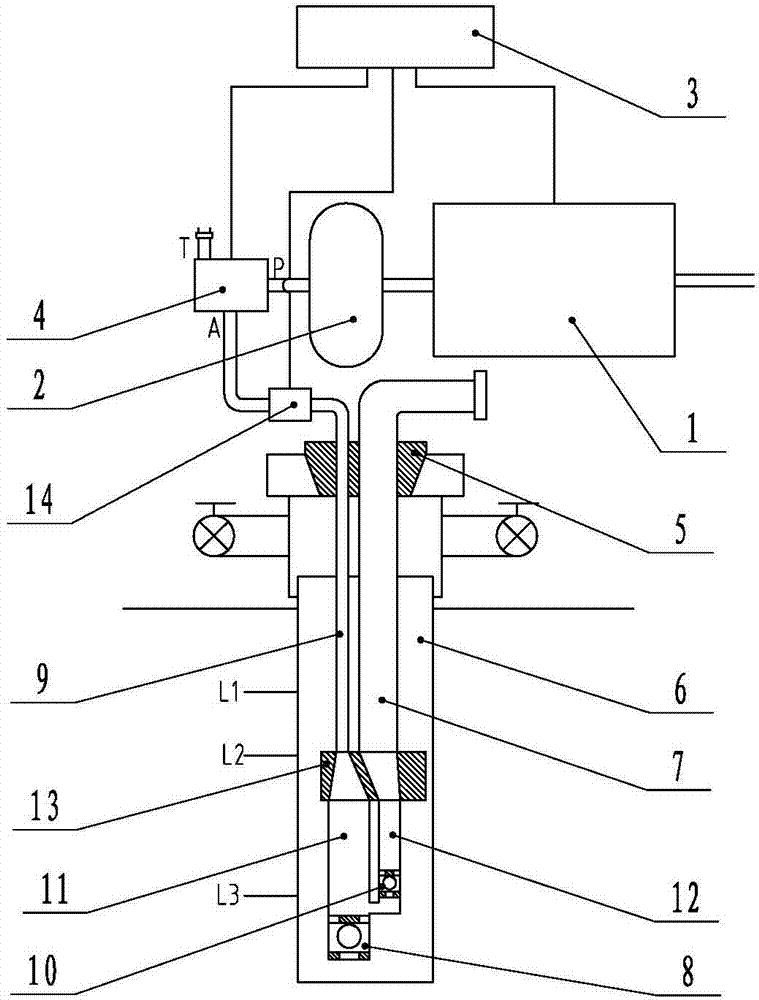
[0030] Embodiment 1: An equipment for forcedly lifting water or oil by gas energy in which the oil discharge pipe and the oil storage pipe are arranged side by side. Such as figure 1 .

[0031] In the field of oil production, the gas-energy equipment for forcibly lifting water or oil includes an oil storage pipe 11, an oil pipe 7 and an oil discharge pipe 12. The oil storage pipe 11 and the oil discharge pipe 12 are arranged in the casing 6 of the oil well, and the well head of the oil well is a sealed well head 5. It is characterized in that: the lower end of the oil storage pipe 11 is fixedly provided with an oil inlet valve 8, the lower end of the oil discharge pipe 12 is fixedly provided with an oil outlet valve 10, the oil inlet of the oil outlet valve 10 and the oil storage pipe 11 above the oil inlet valve 8 The bottom of the inner cavity is connected, the upper end of the oil discharge pipe 12 is connected to the oil pipe 7, the upper end of the oil storage pipe 11 is con...

Embodiment 2

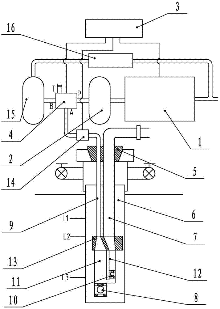
[0042] Embodiment 2: A device for forcedly lifting water or oil by gas energy with a sleeved oil discharge pipe and an oil storage pipe. Such as image 3 .

[0043] In the field of oil production, the gas can forcibly lift water or oil equipment, including oil storage pipe 11, oil pipe 7 and oil discharge pipe 12. The oil storage pipe 11 and the oil discharge pipe 12 are arranged in the casing 6 of the oil well, and the well head of the oil well is a sealed well head 5. It is characterized in that: an oil inlet valve 8 is fixed at the lower end of the oil storage pipe 11, an oil outlet valve 10 is fixed at the lower end of the oil discharge pipe 12, and the oil discharge pipe 12 is sleeved in the cavity of the oil storage pipe 11. The oil inlet of 10 is located at the bottom of the inner cavity of the oil storage pipe 11, the upper end of the oil discharge pipe 12 is connected to the oil pipe 7, and the upper end of the oil storage pipe 11 is connected to the outlet A of the cont...

Embodiment 3

[0051] Example 3: The oil discharge pipe and the oil storage pipe are used side-by-side in a multi-well state, such as Figure 5 .

[0052] In the field of oil production, the gas-energy equipment for forcibly lifting water or oil includes oil storage pipe 11, oil pipe 7 and oil discharge pipe 12. There are oil storage pipe 11 and oil discharge pipe in casing 6 of well 1 and well 2. 12. The wellheads of the oil wells are all sealed wellheads 5, which are characterized in that: an oil inlet valve 8 is fixed at the lower end of the oil storage pipe 11 of each oil well, and an oil outlet valve 10 is fixed at the lower end of the oil discharge pipe 12 of each oil well. The oil inlet of the oil outlet valve 10 in an oil well communicates with the bottom of the inner cavity of the oil storage pipe 11 above the corresponding oil inlet valve 8. The oil storage pipe 11 and the oil discharge pipe 12 in the same oil well are arranged side by side in the casing 6 cavity Inside, the upper end...


PUM


Abstract

The invention discloses a method and equipment for forcibly lifting water or oil by air energy. The method is completed by the following steps that firstly, an oil storage pipe and an oil discharge pipe are firstly arranged in a well casing pipe, each of the lower end of the oil storage pipe and the lower end of the oil discharge pipe is provided with an one-way valve, an inlet of the one-way valve arranged at the lower end of the oil discharge pipe is communicated with the bottom of an inner cavity of the oil storage pipe, a compressor provides high-pressure air energy for a high-pressure air storage tank and stores the high-pressure air energy, the high-pressure air storage tank is communicated with an air inlet of a control valve, an air outlet of the control valve is communicated with the oil storage pipe, when the air inlet and the air outlet are communicated, the high-pressure air can enter the oil storage pipe for pressing the liquid into the oil discharge pipe, finally, and the liquid is lifted onto the ground, so that the air outlet of the control valve is communicated with an exhaust opening, in addition, liquid in the well casing pipe enters an oil storage pipe cavity, and the circulation is repeatedly carried out in such a way. The method and the equipment have the advantages that no moving component is adopted under the ground, the fault rate is low, and the maintenance operation cost is greatly reduced.

Description

Technical field [0001] The invention relates to a method and equipment for extracting groundwater or oil, in particular to a method and equipment for forcibly lifting water or oil by using high-pressure gas energy as power for oil extraction or water extraction. Background technique [0002] At present, water pumps are generally used for water pumping equipment. The methods of oil extraction are mainly rod-based oil extraction and traditional rodless oil extraction technology. The equipment is mainly traditional downhole rod string and oil well pumps, electric submersible pumps, screw pumps and other equipment. In the process of oiling, the sucker pump has the disadvantage of overcoming the sucker rod’s own weight and it is prone to eccentric wear of the rod and tube; the cables and pumps of the electric submersible pump down to the bottom of the well are susceptible to abrasion, and they must be damaged once they are damaged. The pump can be started only after the operation is r...

Claims


Application Information

Patent Timeline
Patent Type & Authority Applications(China)
IPC IPC(8): E21B43/16
CPCE21B43/168E21B43/18
Inventor 宋丕刘马宝忠
Owner SHANDONG WEIMA PUMPS MFG
Why Eureka
Try Eureka