
Spring-loaded pressure regulator

A spring-loaded, pressure regulator technology, applied in the direction of functional valve types, valve details, safety valves, etc., can solve the problems of low pressure adjustment accuracy of the pressure regulator, affecting safe gas supply, unstable pressure downstream of the pressure regulator, etc.

Inactive Publication Date: 2015-04-08
TERRENCE ENERGY
View PDF5 Cites 5 Cited by
  • Summary
  • Abstract
  • Description
  • Claims
  • Application Information

AI Technical Summary

Problems solved by technology

[0004] 1. The pressure regulating mechanism of the pressure regulator only includes a separation diaphragm, a pressure regulating plate, a spring, and an adjustment rod. During the pressure regulation process of the pressure regulating mechanism, the gas pressure often fluctuates. The balance effect between the springs is not good. When the gas pressure under the separation diaphragm is too high, the separation diaphragm is easily affected by high pressure and damaged, which makes the pressure of the pressure regulator unstable and the downstream pressure of the pressure regulator unstable. safe air supply;
[0005] 2. When the valve stem moves up and down, it is prone to deviation, and the pressure adjustment accuracy of the pressure regulator is low;
[0006] 3. The fit between the valve seat and the valve port is not high, the closing performance of the pressure regulator is poor, and the service life is greatly affected;
[0007] 4. When the pressure difference between the left channel and the right channel of the valve body is large or the gas flow rate is large, the pressure at the right channel port will fluctuate, and the gas at the right channel port will be uniformly distributed, resulting in loud noise from the valve body, resulting in sound polution

Method used


Image

  • Spring-loaded pressure regulator

Examples


Embodiment Construction

[0021] The present invention will be further described below in conjunction with the accompanying drawings and specific embodiments.

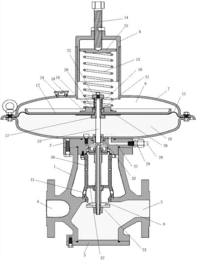
[0022] see figure 1 , when the spring is loaded, the pressure regulator includes a valve body and a main pressure regulating mechanism. The valve body includes a valve body body 1, an upper cover 2, and a lower cover 3. The valve port 6 between the left channel and the right channel, the upper cover and the lower cover are fixedly connected with the upper end and the lower end of the valve body body respectively, and the main pressure regulating mechanism is fixedly connected with the upper cover of the valve body. The main pressure regulating mechanism includes a The housing 7 of the inner cavity, the pressure regulating mechanism arranged in the housing, and the adjusting pressure cap 8 threadedly connected with the upper part of the housing, the pressure regulating mechanism includes the inner cavity of the housing divided into the upper pre...


PUM


Abstract

The invention relates to a spring-loaded pressure regulator, which comprises a valve body and a main pressure regulation mechanism connected with the top of the valve body, a partitioning diaphragm is arranged in the main pressure regulation mechanism, a pressure regulation plate is arranged on the partitioning diaphragm, a main regulation spring seat and an auxiliary regulation spring seat are arranged on the pressure regulation plate, a main regulation spring is arranged on the main regulation spring seat, a valve rod is arranged in the pressure regulator, the upper end of the valve rod sequentially and vertically runs through the partitioning diaphragm, the pressure regulation plate and the auxiliary regulation spring seat and is then screwed in a nut, an auxiliary regulation spring and an inverted T-shaped guide sleeve sleeve the upper end of the valve rod, the upper end and lower end of the auxiliary regulation spring are respectively limited by the nut and a second annular step, the outer sidewall of the vertical part of the inverted T-shaped guide sleeve is in clearance fit with the partitioning diaphragm, the pressure regulation plate and the auxiliary regulation spring seat, and the upper surface of the horizontal part of the inverted T-shaped guide sleeve is in contact with the partitioning diaphragm. The adoption of the solution can effectively prevent the partitioning diaphragm from being damaged by the overhigh pressure of gas under the partitioning diaphragm, consequently, the service life of the pressure regulator is prolonged, and the pressure regulator can more safely supply gas.

Description

technical field [0001] The invention relates to the field of mechanical equipment, in particular to a spring-loaded pressure regulator. Background technique [0002] The existing spring-loaded pressure regulator includes a valve body with a left channel and a right channel, and a main pressure regulating mechanism connected to the upper part of the valve body. There is a separation diaphragm in the mechanism, a pressure regulating plate is arranged on the separation diaphragm, a spring and an adjustment rod are arranged on the pressure regulating plate, a valve stem is arranged under the separation diaphragm, and a valve rod matching the valve port is arranged at the lower end of the valve stem. seat. When in use, the gas pressure under the separation diaphragm is balanced with the spring above the separation diaphragm, so that a gap is created between the valve seat and the valve port for gas to pass through. When the gas pressure changes, the balance between the gas pres...

Claims


Application Information

Patent Timeline
Patent Type & Authority Applications(China)
IPC IPC(8): F16K17/30F16K31/126F16K27/02F16K41/02F16K47/02
CPCF16K17/32F16K27/02F16K31/1262F16K41/02F16K47/02
Inventor 姚保纯王建忠吴振华史佳
Owner TERRENCE ENERGY
Learn More