Cable drying device

A drying device and cable technology, applied in the direction of cable/conductor manufacturing, circuits, electrical components, etc., can solve the problems of ineffective recycling of cables, waste of water resources, damage to spark machines, etc., to achieve simple structure and increase cleanliness , Increase the effect of water removal capacity

Inactive Publication Date: 2015-04-08
江苏辰宇电气有限公司
View PDF0 Cites 12 Cited by
  • Summary
  • Abstract
  • Description
  • Claims
  • Application Information

AI Technical Summary

Problems solved by technology

[0002] In the process of cable processing, in order to cool the cable after extruding the sheath, the method of immersing the cable in the water tank after the extrusion head is used to reduce the temperature of the cable and solidify the sheath material, so there are more water droplets on the surface of the cable after it exits the water tank. On the surface, in order to prevent the spark machine from being damaged by the water brought out, a drying device is generally installed behind the sink. The traditional method of drying the cable is to blow the cable through a cylindrical blowing port of a fixed size, but due to the width of the blowing port limited, and the cable moves faster, there will often be water marks on the surface of the cable, and the water dripping from the surface of the cable during the drying process cannot be effectively recycled, and it is a waste of water resources

Method used


Image

  • Cable drying device
  • Cable drying device

Examples


Embodiment Construction

[0013] The technical solution of this patent will be further described in detail below in conjunction with specific embodiments.

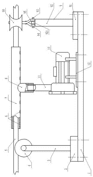
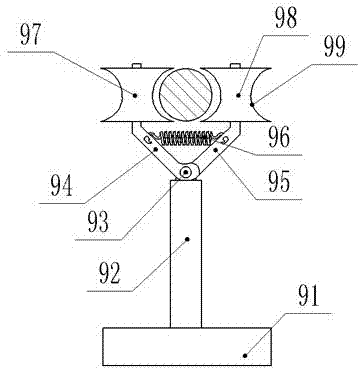
[0014] see Figure 1-2 , a cable drying device, comprising a base plate 1, a cable 5, a blower 10 and a water removal device 9, the upper left side of the base plate 1 is fixedly connected to a roller base 2 by bolts, and the upper end of the roller base 2 is vertically provided with a roller support rod 3. The upper end of the roller support rod 3 is rotated to connect with the roller 4, and the middle part of the roller 4 is provided with an annular groove, and the roller 4 can support and guide the cable; the blower 10 is arranged on the right side of the roller 4, and The lower end of the blower 10 is fixed on the fan base 12, and the fan base 12 is fixedly installed on the base plate 1 by bolts. An air duct 7 is welded on the upper end of the air duct 7, and a cable 5 is connected inside the air duct 7. When the diameter of the cable 5 is lar...


PUM

PropertyMeasurementUnit
lengthaaaaaaaaaa

Abstract

The invention discloses a cable drying device, which comprises a bottom plate, a cable, a blower and a dehydrating device, wherein the top left of the bottom plate is fixedly connected with an idler wheel base through a bolt, an idler wheel support rod is vertically arranged at the upper end of the idler wheel base, the upper end of the idler wheel support rod is in rotating connection with an idler wheel, an annular groove is arranged in the middle of the idler wheel, the blower is arranged at the right side of the idler wheel, the lower end of the blower is fixed on a draught fan base, which is fixedly arranged on the bottom plate through the bolt, the upper end of the blower is connected with an air hose, the upper end of the air hose is connected with a shunt pipe through threads, an air duct is welded at the upper end of the shunt pipe, the cable is arranged in the air duct, and a plurality of drainage exits are arranged at the bottom of the air duct. The cable drying device has a simple structure, is convenient to use, and keeps the surface of the cable clearer; and the air duct further improves the dehydration capacity of the device, and protects a spark machine from being damaged by water on the cable.

Description

technical field [0001] The invention relates to a cable manufacturing machine, in particular to a cable drying device. Background technique [0002] In the process of cable processing, in order to cool the cable after extruding the sheath, the method of immersing the cable in the water tank after the extrusion head is used to reduce the temperature of the cable and solidify the sheath material, so there are more water droplets on the surface of the cable after it exits the water tank. On the surface, in order to prevent the spark machine from being damaged by the water brought out, a drying device is generally installed behind the sink. The traditional method of drying the cable is to blow the cable through a cylindrical blowing port of a fixed size, but due to the width of the blowing port Limited, and the movement speed of the cable is fast, there are often water marks left on the surface of the cable, and the water dripping from the surface of the cable during the dry...

Claims


Application Information

Patent Timeline
Patent Type & Authority Applications(China)
IPC IPC(8): H01B13/30
Inventor 王立
Owner 江苏辰宇电气有限公司
Why Eureka
Try Eureka