
Wafer clamping device

A clamping device and wafer technology, applied in electrical components, semiconductor/solid-state device manufacturing, circuits, etc., can solve problems such as inconvenient operation, wafer cleaning machine errors, alarms, etc., and achieve simple structure, convenient operation, and convenient movement Effect

Inactive Publication Date: 2015-04-08
SUZHOU KAIDE MICRO ELECTRONICS CO LTD
View PDF5 Cites 0 Cited by
  • Summary
  • Abstract
  • Description
  • Claims
  • Application Information

AI Technical Summary

Problems solved by technology

After CMP, the wafer needs to be cleaned. There is a wafer cleaning machine in the prior art, but in the actual manufacturing process, the wafer cleaning machine will make an error and give an alarm. At this time, it is necessary to manually transfer the wafer, so the wafer needs to Clamping device
[0003] Chinese patent (201420149283.1) discloses a wafer grabbing tool. This utility model realizes the clamping and fixing of the wafer by stretching and resetting the spring, but the device operates in parallel with the wafer, and the bracket arm is easy to touch to the wafer surface, and inconvenient to operate

Method used


Image

  • Wafer clamping device
  • Wafer clamping device

Examples


Embodiment Construction

[0016] The present invention will be further described below in conjunction with the accompanying drawings. The following examples are only used to illustrate the technical solution of the present invention more clearly, but not to limit the protection scope of the present invention.

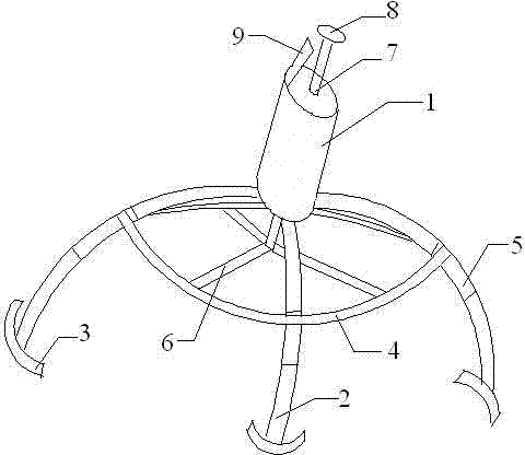
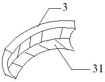
[0017] like figure 1 As shown, a wafer clamping device is characterized in that it includes a handle bar 1, an arc-shaped grab bar 2, a clamping part 3 and a hoop 4 located on the arc-shaped grab bar 2; the arc-shaped grab bar The upper end of the bar 2 is connected to the lower end of the grip bar 1, and the lower end of the arc grab bar 2 is connected to the clamping part 3; the inside of the grip bar 1 is provided with a movable pressing bar 7, and the lower end of the pressing bar 7 is connected to three a push rod 6; the other end of the push rod 6 is located on the hoop 4;

[0018] The top end of the pressing rod 7 is provided with a pressing cap 8, and the pressing cap 8 is made of rubb...


PUM


Abstract

The invention discloses a wafer clamping device, which is characterized by comprising a holding rod (1), cambered grasping rods (2), clamping parts (3) and a hoop (4) positioned on the cambered grasping rods (20, wherein the upper ends of the cambered grasping rods (2) are connected to the lower end of the holding rod (1); the clamping parts (3) are connected to the lower ends of the cambered grasping rods (2); a movable pressing rod (7) is arranged in the holding rod (1); three pushrods (6) are connected to the lower end of the pressing rod (7); the other ends of the pushrods (6) are positioned on the hoop (4); a buckle (9) is arranged at the top end of the holding rod (1); sliding chutes (5) are formed in the same positions of the cambered grasping rods (2); the hoop (4) is positioned on the sliding chutes (5). The wafer clamping device is simple in structure, stable and convenient to operate, and the surface of the wafer is difficult to collide.

Description

technical field [0001] The invention relates to the field of semiconductor manufacturing, in particular to a wafer clamping device. Background technique [0002] In wafer manufacturing, chemical mechanical polishing (CMP) technology is used to globally planarize the surface of the wafer. CMP chemical mechanical polishing technology combines the advantages of chemical polishing and mechanical polishing, and can obtain a more perfect surface while ensuring material removal efficiency. The flatness is 1-2 orders of magnitude higher than the pure use of these two types of grinding, and can achieve surface roughness from the nanometer level to the atomic level. After CMP, the wafer needs to be cleaned. There is a wafer cleaning machine in the prior art, but in the actual manufacturing process, the wafer cleaning machine will make an error and give an alarm. At this time, it is necessary to manually transfer the wafer, so the wafer needs to clamping device. [0003] Chinese pate...

Claims


Application Information

Patent Timeline
Patent Type & Authority Applications(China)
IPC IPC(8): H01L21/687
CPCH01L21/687
Inventor 刘思佳
Owner SUZHOU KAIDE MICRO ELECTRONICS CO LTD
Learn More