Concentric ring-shaped clearance draft fan airflow nozzle

A technology of concentric rings and nozzles, applied in the direction of injection devices, injection devices, etc., can solve the problems of large fan air flow nozzles, no air flow, no mature technology, etc., and achieve long range, good blowing effect, and concentrated airflow Effect

Inactive Publication Date: 2015-04-15
NINGXIA JIAXIANG AUTOMATIC CONTROL TECH
View PDF7 Cites 0 Cited by
  • Summary
  • Abstract
  • Description
  • Claims
  • Application Information

AI Technical Summary

Problems solved by technology

[0002] At present, in the metallurgical industry: such as iron and steel smelting and metal magnesium smelting, there are many process links that require the use of large flow and low pressure fan airflow to remove smelting waste, while domestic gas purging nozzles are all compressed air The purge nozzle with air source is only suitable for the purge requirements of small flow and high pressure, but there is no mature technology for the purge nozzle with fan airflow as the air source with large flow and low pressure; on the other hand, there is no mature technology for equipment, The large-area cooling of the tank also uses a nozzle that combines compressed air and liquid to atomize, and there is no fan airflow nozzle with a large air flow.

Method used


Image

  • Concentric ring-shaped clearance draft fan airflow nozzle

Examples


Embodiment 1

[0011] Embodiment 1 Composition of a concentric annular gap nozzle of fan airflow and the effect of each component:

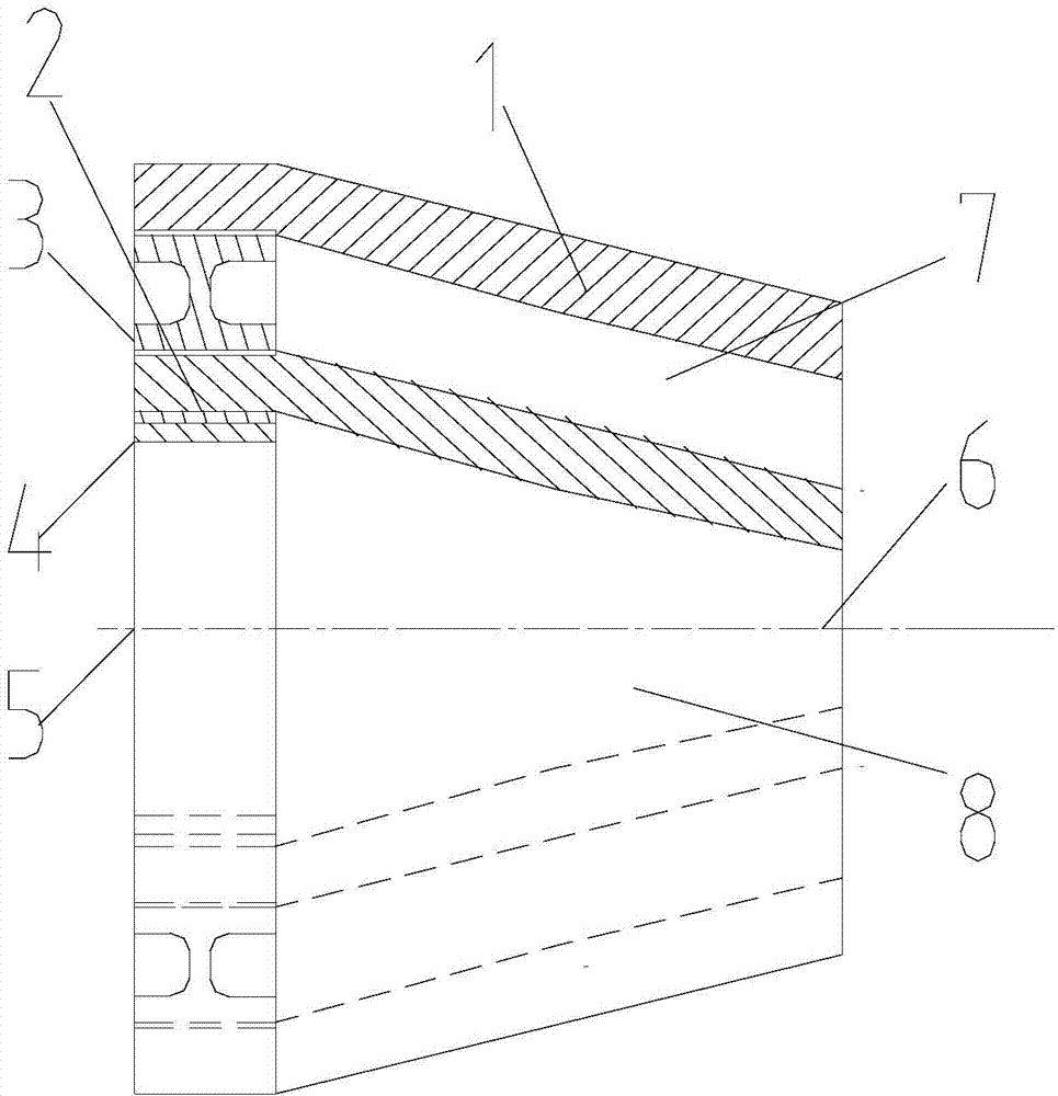
[0012] A concentric annular gap nozzle includes an outer nozzle 1, an inner nozzle 2, an inner and outer nozzle connector 3, an inner and outer nozzle connector middle circular gasket 4, a nozzle inlet 5, a nozzle outlet 6, and an outer nozzle cavity 7 . The inner nozzle cavity 8 is characterized in that the concentric annular gap nozzle is a double-layer hollow nozzle, and the size of the gap and the intercepted area of ​​the cavity are adjusted by adjusting the number of circular gaskets 4 in the middle of the inner and outer nozzle connectors. The inclination angle of the nozzle is 15°. There are external threads and internal threads on the inner and outer nozzle connecting body 3, the external threads are used to connect the outer layer nozzle 1, and the internal threads are used to connect the inner layer nozzle 2, and are used to connect the nozzles and...

Embodiment 2

[0013] Embodiment 2 Working principle of a concentric annular gap nozzle for fan air flow:

[0014] The air flow of the fan enters from the nozzle inlet 5, and then passes through the outer nozzle cavity 7, the inner nozzle cavity 8, and the nozzle outlet 6, and the outer nozzle cavity 7, the inner nozzle cavity 8 from the nozzle inlet 5 to the nozzle outlet 6 The streamlined design minimizes the drag coefficient. After exiting from the nozzle outlet 6, the outer layer airflow suppresses the inner layer airflow to diffuse the airflow column, so the range is long and the impact is strong.


PUM


Abstract

The invention relates to a concentric ring-shaped clearance draft fan airflow nozzle. The concentric ring-shaped clearance draft fan airflow nozzle comprises an outer-layer nozzle 1, an inner-layer nozzle 2, an inner-layer nozzle and outer-layer nozzle connector 3, inner-layer nozzle and outer-layer nozzle connector middle round gaskets 4, a nozzle inlet 5, a nozzle outlet 6, an outer-layer nozzle cavity 7 and an inner-layer nozzle cavity 8. The concentric ring-shaped clearance draft fan airflow nozzle is characterized in that the concentric ring-shaped clearance draft fan airflow nozzle is a double-layer hollow nozzle; the clearance size and the retaining area of the cavities are adjusted by adjusting the number of the inner-layer nozzle and outer-layer nozzle connector middle round gaskets 4, and the inclination angle of the concentric ring-shaped clearance draft fan airflow nozzle is 15 degrees. The concentric ring-shaped clearance draft fan airflow nozzle has advantage of being capable of adjusting the number of the round gaskets to adjust the volume of the double-layer cavity and further to change the purging effects, thereby being long in jetting range, concentrated in air flow and high in purging effects.

Description

technical field [0001] The invention relates to a concentric annular gap nozzle for fan air flow, belonging to the technical field of nozzles. Background technique [0002] At present, in the metallurgical industry: such as iron and steel smelting and metal magnesium smelting, there are many process links that require the use of large flow and low pressure fan airflow to remove smelting waste, while domestic gas purging nozzles are all compressed air The purge nozzle with air source is only suitable for the purge requirements of small flow and high pressure, but there is no mature technology for the purge nozzle with fan airflow as the air source with large flow and low pressure; on the other hand, there is no mature technology for equipment, The cooling of the large area of ​​the tank also uses the nozzle of compressed air and liquid combined with atomization, and there is no fan air flow nozzle with large air flow. Contents of the invention [0003] The purpose of the...

Claims


Application Information

Patent Timeline
Patent Type & Authority Applications(China)
IPC IPC(8): B05B1/34
CPCB05B1/10
Inventor 李黎
Owner NINGXIA JIAXIANG AUTOMATIC CONTROL TECH
Why Eureka
Try Eureka