Compound reamer for valve port

A kind of reamer and valve hole technology, applied in the direction of reamer, reaming device, metal processing equipment, etc., can solve the problems of shortening the life of the cutter body, hindering the heat dissipation of the cutter body, complicated valve structure, etc., so as to improve the service life and structure. Practical and simple structure

Inactive Publication Date: 2015-04-15
常州苏科工具有限公司
View PDF0 Cites 0 Cited by
  • Summary
  • Abstract
  • Description
  • Claims
  • Application Information

AI Technical Summary

Problems solved by technology

[0002] In mechanical processing, chips are not easy to get rid of during the cutting process, and the chips are easy to tangle. The chips generated by the existing cutting tools are blocked by the end face of the tool shaft, so it is not easy to get rid of them smoothly, and even stick to the tool body due to high temperature, which seriously hinders the cutting process. The heat dissipation of the cutter body shortens the life of the cutter body, and the chips adhering to the cutter body tend to scratch the surface of the workpiece, which cannot make the processed surface smooth, especially after the first processing of gas and liquid valves. The surface of the workpiece needs to be smooth and free of scratches during the second processing. Due to the complex internal structure of the valve, ordinary tools cannot complete this work.

Method used


Image

  • Compound reamer for valve port
  • Compound reamer for valve port

Examples


Embodiment Construction

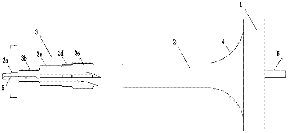
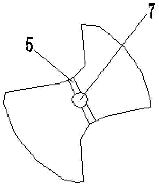
[0010] like figure 1 As shown, a compound reamer for a valve hole includes a reamer disc 1, a reamer rod 2 and a reamer head 3, and the reamer head includes a first-stage cutter head 3a, a second-stage cutter head 3b, and a third-stage cutter head 3c , the fourth-order cutter head 3d and the fifth-order cutter head 3e, the cutter head 1 and the reamer bar 2 are connected by an arc surface 4, the first-order cutter head 3a is provided with a coolant outlet 5, and the reamer head 1 is provided with a cooling The liquid inlet pipe 6 , the reamer rod 2 and the reamer head 1 are provided with a coolant channel 7 , and the coolant channel 7 communicates with the coolant inlet pipe 6 and the coolant outlet 5 .

[0011] The coolant outlet is located at the bottom of the chip removal groove of the reamer head.


PUM


Abstract

The invention belongs to the field of cutting tools and particularly relates to a compound reamer for a valve port. The compound reamer for the valve port comprises a reamer plate, a reamer rod and a reamer head. The reamer head comprises a first-order reamer head, a second-order reamer head, a third-order reamer head, a fourth-order reamer head and a fifth-order reamer head. The reamer plate is connected with the reamer rod through an arc surface. The first-order reamer head is provided with a cooling liquid outlet. The reamer plate is provided with a cooling liquid inlet pipe. A cooling liquid channel is formed inside the reamer rod and the reamer head. The cooling liquid channel is communicated with the cooling liquid inlet pipe and the cooling liquid outlet pipe. The compound reamer for the valve port has the advantages of being simple and practical in structure, and can be processed and formed one time when reaming and cooled real time so that the service life of the reamer is prolonged.

Description

technical field [0001] The invention belongs to the field of cutting tools, in particular to a composite reamer for valve holes. Background technique [0002] In mechanical processing, chips are not easy to get rid of during the cutting process, and the chips are easy to tangle. The chips generated by the existing cutting tools are blocked by the end face of the tool shaft, so it is not easy to get rid of them smoothly, and even stick to the tool body due to high temperature, which seriously hinders the cutting process. The heat dissipation of the cutter body shortens the life of the cutter body, and the chips adhering to the cutter body tend to scratch the surface of the workpiece, which cannot make the processed surface smooth, especially after the first processing of gas and liquid valves. The surface of the workpiece needs to be smooth and free of scratches during the second processing. Due to the complex internal structure of the valve, ordinary tools cannot complete th...

Claims


Application Information

Patent Timeline
Patent Type & Authority Applications(China)
IPC IPC(8): B23D77/00
Inventor 恽雪燕
Owner 常州苏科工具有限公司
Why Eureka
Try Eureka