Connecting rod type workpiece machining device

A processing device and connecting rod technology, applied in the field of workpiece processing, can solve the problems of high equipment cost and unstable transmission, and achieve the effects of low cost, avoiding workpiece wear and simple structure

Inactive Publication Date: 2015-04-15
CHONGQING QUANHAI MACHINERY
View PDF0 Cites 1 Cited by
  • Summary
  • Abstract
  • Description
  • Claims
  • Application Information

AI Technical Summary

Problems solved by technology

[0003] The purpose of the present invention is to provide a link-type workpiece processing device to solve the...

Method used


Image

  • Connecting rod type workpiece machining device

Examples


Embodiment Construction

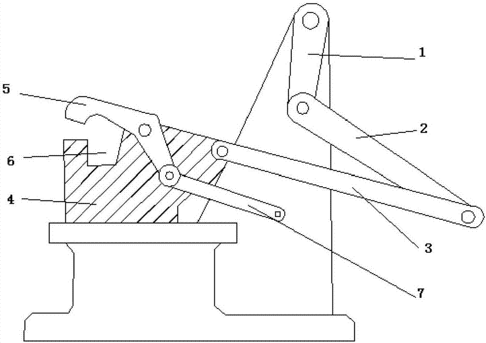
[0012] The reference signs in the description of the drawings are: crank 1, rotating swing rod 2, push connecting rod 3, processing boss 4, curved clamp body 5, clamping part 6, linkage arm 7.

[0013] Such as figure 1 As shown, the technical solution provides a link-type workpiece processing device, including a frame, a control device and a clamping device. The control device includes a crank 1, a rotating swing rod 2 and a push connecting rod 3, and the ratio of the length of the rotating swing rod 2 to the length of the crank 1 is 2:1. The crank 1 is rotatably connected to the frame and driven to rotate by the motor. The lower end of the crank 1 is hinged on the upper end of the rotating fork 2 , and the lower end of the rotating fork 2 is hinged on the left end of the push connecting rod 3 .

[0014] The clamping device includes a processing boss 4 and a curved clamp body 5, the right end of the processing table is hinged on the free end of the push connecting rod 3, and...


PUM


Abstract

The invention relates to a connecting rod type workpiece machining device. The connecting rod type workpiece machining device comprises a rack, a control device and a clamping device, wherein the control device comprises a crank, a rotary swinging rod and a push connecting rod; the control device comprises the crank, the rotary swinging rod and the push connecting rod; the crank is rotationally connected with the rack and is hinged with one end of the rotary swinging rod; the other end of the rotary swinging rod is hinged with the push connecting rod; the clamping device comprises a machining bulge and a curve-shaped clamp body; a machining platform is hinged with the free end of the push connecting rod; the machining bulge is horizontally and slidingly connected with the rack; the machining bulge is provided with a clamping part for containing a workpiece; the middle part of the curve-shaped clamp body is hinged with the machining platform close to one end of the clamping part; a clamping claw for clamping the workpiece is formed by the curve-shaped clamp body and the clamping part; one end of the curve-shaped clamp body is connected with a linkage arm and the other end of the linkage arm is hinged with the rack. With the adoption of the connecting rod type workpiece machining device, the problem that the conveying is not stable or the equipment cost is high in an existing workpiece conveying process is solved.

Description

technical field [0001] The invention relates to the field of workpiece processing, in particular to a connecting rod type workpiece processing device. Background technique [0002] In workpiece production, processing and manufacturing, workpieces need to be transferred between every two processing stations. At present, CNC equipment or transmission belts are generally used to transfer workpieces. As for the CNC sorting method, since such equipment often needs to be debugged and the price is high, it is usually not suitable for small processing plants. For the way of conveyor belt, there are many uncertain factors in the transmission of workpieces in the conveyor belt, especially for circular workpieces. During the transmission process, if the workpieces are not well positioned, the workpieces will roll around and collisions will occur between workpieces. , mutual friction, etc., which may cause greater wear on the workpiece, thereby affecting the quality of the workpiece. ...

Claims


Application Information

Patent Timeline
IPC IPC(8): B65G47/90
Inventor 张水泉
Owner CHONGQING QUANHAI MACHINERY
Why Eureka
Try Eureka