Multifunctional longitudinal movement driving device for bridge girder erection machine

A technology of a driving device and a bridge erecting machine, which is applied in the direction of erecting/assembling bridges, bridges, walking mechanisms, etc., can solve the problems of difficulty in arranging via-hole walking driving mechanisms, difficult layout of wheel driving mechanisms, and difficulty in providing driving force, etc. The effect of compactness, high driving force and low manufacturing cost

Active Publication Date: 2015-04-15
ZHENGZHOU NEW DAFANG HEAVY IND & TECH
View PDF6 Cites 4 Cited by
  • Summary
  • Abstract
  • Description
  • Claims
  • Application Information

AI Technical Summary

Problems solved by technology

However, for bridges with a longitudinal slope exceeding 3%, it is difficult to provide a suitable driving force by relying on the adhesion between the wheels and the track. At the same time, the large slope often leads to slippery phenomena, especially in rainy and snowy weather. , the friction coefficient between the wheel and the track is smaller, which increases the safety risk
[0003] For the through-hole driving method of the bridge erecting machine, the motor + reducer is generally arranged on the outriggers to drive the wheels. However, due to the limitation of the working space of the outriggers, it is difficult to arrange the wheel drive mechanism, especially for large-tonnage bridge erecting machines. , it is very difficult to arrange the via-hole driving mechanism in the limited working space of the outrigger

Method used


Image

  • Multifunctional longitudinal movement driving device for bridge girder erection machine
  • Multifunctional longitudinal movement driving device for bridge girder erection machine
  • Multifunctional longitudinal movement driving device for bridge girder erection machine

Examples


Embodiment Construction

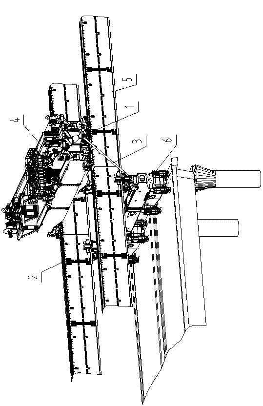
[0021] Such as figure 1 , figure 2 , image 3 and Figure 4 As shown, the multifunctional longitudinal movement drive device for a bridge erecting machine of the present invention includes a drive module 1 arranged on the bridge erecting machine crane 4, a drive chain 2 on the bridge erecting machine main girder 5, and a bridge erecting machine crane 4 and the strut mechanism 3 between the main legs 6.

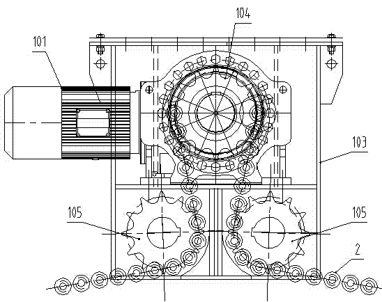
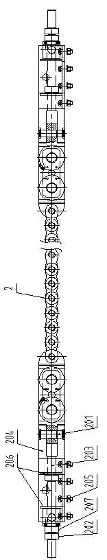
[0022] Drive module 1 comprises drive casing 103, reduction motor 101, drive sprocket 104 and two driven sprockets 105, reduction motor 101 is located on the drive casing 103, and drive sprocket 104 and two driven sprockets 105 are set In the drive box 103, the power drive end of the reduction motor 101 is connected to the drive sprocket 104 in transmission, and the two driven sprockets 105 are respectively located at the front side and the rear side below the drive sprocket 104, and the front and rear ends of the drive chain 2 are respectively It is fixedly connected wit...


PUM


Abstract

A multifunctional longitudinal movement driving device for a bridge girder erection machine comprises a driving module arranged on a crown block of the bridge girder erection machine, driving chains on main beams of the bridge girder erection machine and a support rod mechanism between the crown block of the bridge girder erection machine and a main landing leg. Longitudinal movement of the crown block of the bridge girder erection machine and via holes of the main beams can be achieved by one drive mechanism; the problems of insufficient driving power, operation skid, difficult mechanism layout and the like of the bridge girder erection machine during long-span, large-tonnage and heavy-grade bridge construction can be solved; and the device has the characteristics of safety, stability, low cost, compact mechanism layout and the like.

Description

technical field [0001] The invention belongs to the technical field of bridge construction, and in particular relates to a multifunctional longitudinal movement driving device for a bridge erecting machine. Background technique [0002] At present, the driving method of the crane crane of the bridge erecting machine is mainly the motor + reducer to drive the wheels, which require the wheels to overcome the friction between the track and the bridge. This method is mainly used for the construction of bridges with small slopes. Good results. However, for bridges with a longitudinal slope of more than 3%, it is difficult to provide a suitable driving force by the adhesion between the wheels and the track. At the same time, due to the large slope, slippery phenomena often occur, especially in rainy and snowy weather. , the friction coefficient between the wheel and the track is smaller, which increases the safety risk. [0003] For the through-hole driving method of the bridge ...

Claims


Application Information

Patent Timeline
Patent Type & Authority Applications(China)
IPC IPC(8): B66C9/14E01D21/00
CPCB66C9/14E01D21/00
Inventor 宫占斌吴耀辉巩立辉高金涛周治国林建青娄瑞娟王琪胡卫峰
Owner ZHENGZHOU NEW DAFANG HEAVY IND & TECH
Why Eureka
Try Eureka