
Hydraulic support column cap for coal mine

A technology of hydraulic supports and coal mines, which is applied in mine roof supports, mining equipment, earthwork drilling and mining, etc. It can solve the problems of hidden dangers in the safety management of working faces, the inability of supports to lift and move by themselves, and difficulty in ensuring the initial support force of supports. Achieve the effect of simple manufacturing process, simple installation and satisfying working resistance

Inactive Publication Date: 2015-04-15
HUAIBEI MINING IND
View PDF6 Cites 0 Cited by
  • Summary
  • Abstract
  • Description
  • Claims
  • Application Information

AI Technical Summary

Problems solved by technology

[0003] If the top beam of the hydraulic support is damaged or even penetrated, the support cannot be lifted and moved by itself, and the initial support force is difficult to guarantee, which brings great safety hazards to the safety management and production of the working face
In the prior art, two single pillars are generally supported under the top beam of the support, but the support force of the single pillar is far less than the rated support force of the hydraulic support pillar, especially when the pressure is cycled, it is difficult to guarantee the initial support force of the support
At the same time, the excessive load on the single pillar for a long time is prone to accidents such as collapse of the pillar and the escape of the three-purpose valve, which poses a serious threat to safe production

Method used


Image

  • Hydraulic support column cap for coal mine
  • Hydraulic support column cap for coal mine
  • Hydraulic support column cap for coal mine

Examples


Embodiment Construction

[0017] Below with reference to the accompanying drawings, through the description of the embodiments, the specific embodiments of the present invention, such as the shape, structure, mutual position and connection relationship between the various parts, the role and working principle of the various parts, etc., will be further described. detailed instructions.

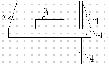
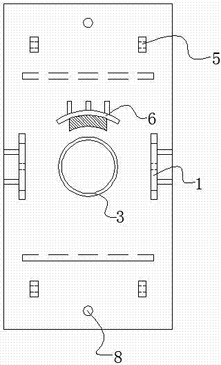
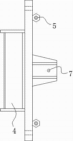
[0018] Such as figure 1 , 2 Shown in , 3, is the structural representation of the present invention, installation column one 1 and installation column two 2 are correspondingly vertically fixed on the side surface of base plate 11, and cylindrical guardrail 3 is fixed on the central position of base plate 11, and cylindrical guardrail periphery is provided with Reinforced steel plate 6, cylindrical guardrail 3 and the top clearance of column 9 cooperate, and the reinforced steel plate 6 that is arranged on the periphery prevents cylindrical guardrail 3 from being deformed by force, and plays the effect of reinforcing ...


PUM


Abstract

The invention discloses a hydraulic support column cap for a coal mine and belongs to the field of hydraulic supports for coal mines. The hydraulic support column cap comprises a base plate and a first installation column and a second installation column which are arranged on the base plate. The first installation column and the second installation column are fixed on the same side of the base plate correspondingly and vertically. An installation hole is formed in each installation column, and a reinforcing block is arranged on the other side of the base plate. The hydraulic support column is simple in manufacture process and simple to install. A guardrail and the columns are in interface fit and ensure that the column cap can be used for hydraulic supports of most types. Meanwhile, the base plate of the column cap is long, and the integrity of a middle beam of the hydraulic support is fully utilized to improve pressure resistance. After the column cap is used, the effect is remarkable, the columns of the support have the reliable support points, and the requirements for support lifting resistance and rated working resistance can be met under the condition that two columns of the support are destroyed.

Description

technical field [0001] The invention relates to the field of coal mine hydraulic support, in particular, the invention relates to a column cap of a coal mine hydraulic support. Background technique [0002] The hydraulic support column cap is located in the gap between the two inner and outer main ribs of the top beam of the hydraulic support. In order to realize the change of the coal mining height of the hydraulic support itself. In addition to bearing the pressure of the roof of the mining area, the top beam of the hydraulic support also bears horizontal friction and lateral force. The force situation is relatively complicated and harsh, and it is easy to be damaged. Therefore, the column cap in the hydraulic support is an important force-bearing part of the hydraulic support. [0003] If the top beam of the hydraulic support is damaged or even penetrated, the support cannot be lifted and moved by itself, and the initial support force is difficult to guarantee, which ...

Claims


Application Information

Patent Timeline
Patent Type & Authority Applications(China)
IPC IPC(8): E21D23/06
CPCE21D23/06
Inventor 林卫国王浩付赵权于驰李勤徐艳
Owner HUAIBEI MINING IND
Learn More