Brake device of pumping unit

A technology of braking device and pumping unit, applied in the field of machinery, can solve problems such as difficulty in braking, and achieve the effect of tight engagement and effort-saving braking

Inactive Publication Date: 2015-04-15
秦浩宇
View PDF0 Cites 1 Cited by
  • Summary
  • Abstract
  • Description
  • Claims
  • Application Information

AI Technical Summary

Problems solved by technology

[0002] At present, the brake device in the prior art is a hoop type brake device, which consists of two brake

Method used


Image

  • Brake device of pumping unit

Examples


Embodiment Construction

[0009] The present invention will be specifically described below in conjunction with the accompanying drawings and embodiments.

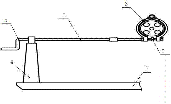
[0010] figure 1 Shown is the structural representation of the present invention.

[0011] The present invention includes a support 1, a rocker 2 and a brake hoop 3. The rocker 2 is arranged on the rocker bracket 4 of the support 1. The brake hoop 3 is an arcuate structure, and the two ends of the arcuate structure are provided with reverse Internally threaded, one end of the rocker 2 is a rocker 5, and the other end is provided with a positioning ring 6, and the rocker 2 on both sides of the positioning ring 6 is provided with reverse threads, and when the rocker 2 rotates, it drives the arc structure. Both ends are tightened or expanded along the reverse internal thread.

[0012] The brake hoop 3 is an arcuate structure composed of two arcuate pieces through movable hinges.

[0013] When in use: the rocking handle 5 is shaken to drive the rocki...


PUM


Abstract

The invention discloses a brake device of a pumping unit. The brake device comprises a supporting seat, a rocking bar and a brake hoop, wherein the rocking bar is arranged on a rocking bar support of the supporting seat; the brake hoop has an arch structure; two ends of the arch structure are provided with reverser inner threads; one end of the rocking bar is provided with a rocking handle, and the other end of the rocking bar is provided with a positioning ring; the rocking bar on two sides of the positioning ring is provided with reverse threads; the rocking bar rotates to drive two ends of the arch structure to shrink or expand along the reverse inner threads; and the brake hoop has the arch structure which consists of two movably-hinged arch pieces. Compared with the traditional two brake devices in the prior art, the novel brake device is provided with an arch-shaped brake hoop, and the arch brake is depended on when the pumping unit is started, so that the braking is labor-saving, compact in cohesion, safe and reliable.

Description

technical field [0001] The invention relates to a braking device for an oil pumping unit, which belongs to the technical field of machinery. Background technique [0002] The brake device of the prior art is a hoop type brake device at present, and two brake pads are in the hoop type to realize braking by tensioning the cable, which is difficult to brake in general. Contents of the invention [0003] The technical problem to be solved by the present invention is to provide a safe and reliable brake device for the deficiencies of the prior art. [0004] In order to solve this technical problem, the present invention provides a brake device for pumping units, which includes a support, a rocker and a brake hoop, the rocker is arranged on the rocker bracket of the support, and the brake hoop has a bow-shaped structure , the two ends of the bow-shaped structure are provided with reverse internal threads, one end of the rocker is a rocker, and the other end is provided with a p...

Claims


Application Information

Patent Timeline
IPC IPC(8): F16D49/00F16D65/06
Inventor 秦浩宇
Owner 秦浩宇
Why Eureka
Try Eureka