Absolute position measurement method

A technology of absolute position and measurement method, which is applied in the direction of transmitting sensing components with optical devices, can solve the problem of low code utilization rate, achieve the effect of reducing the difficulty of code design, improving anti-pollution ability, and improving code utilization rate

Inactive Publication Date: 2015-04-15
CHANGCHUN INST OF OPTICS FINE MECHANICS & PHYSICS CHINESE ACAD OF SCI
View PDF9 Cites 3 Cited by
  • Summary
  • Abstract
  • Description
  • Claims
  • Application Information

AI Technical Summary

Problems solved by technology

[0007] The present invention provides an absolute position measurement method to solve the problem that the existing method is only applicable to the Manchester coding method, and needs to scan additional codes and additional codes specially used for error detection, resulting in low utilization rate of codes.

Method used


Image

  • Absolute position measurement method
  • Absolute position measurement method
  • Absolute position measurement method

Examples


specific Embodiment approach 1

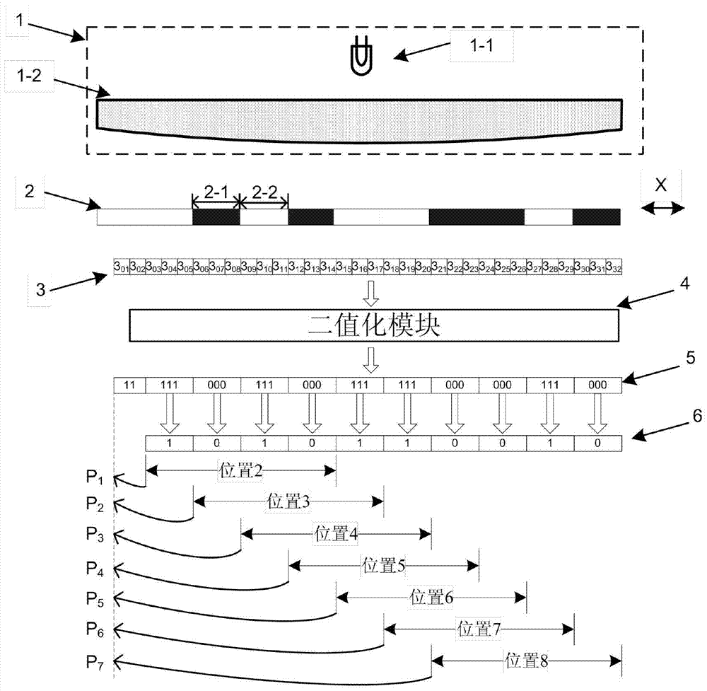
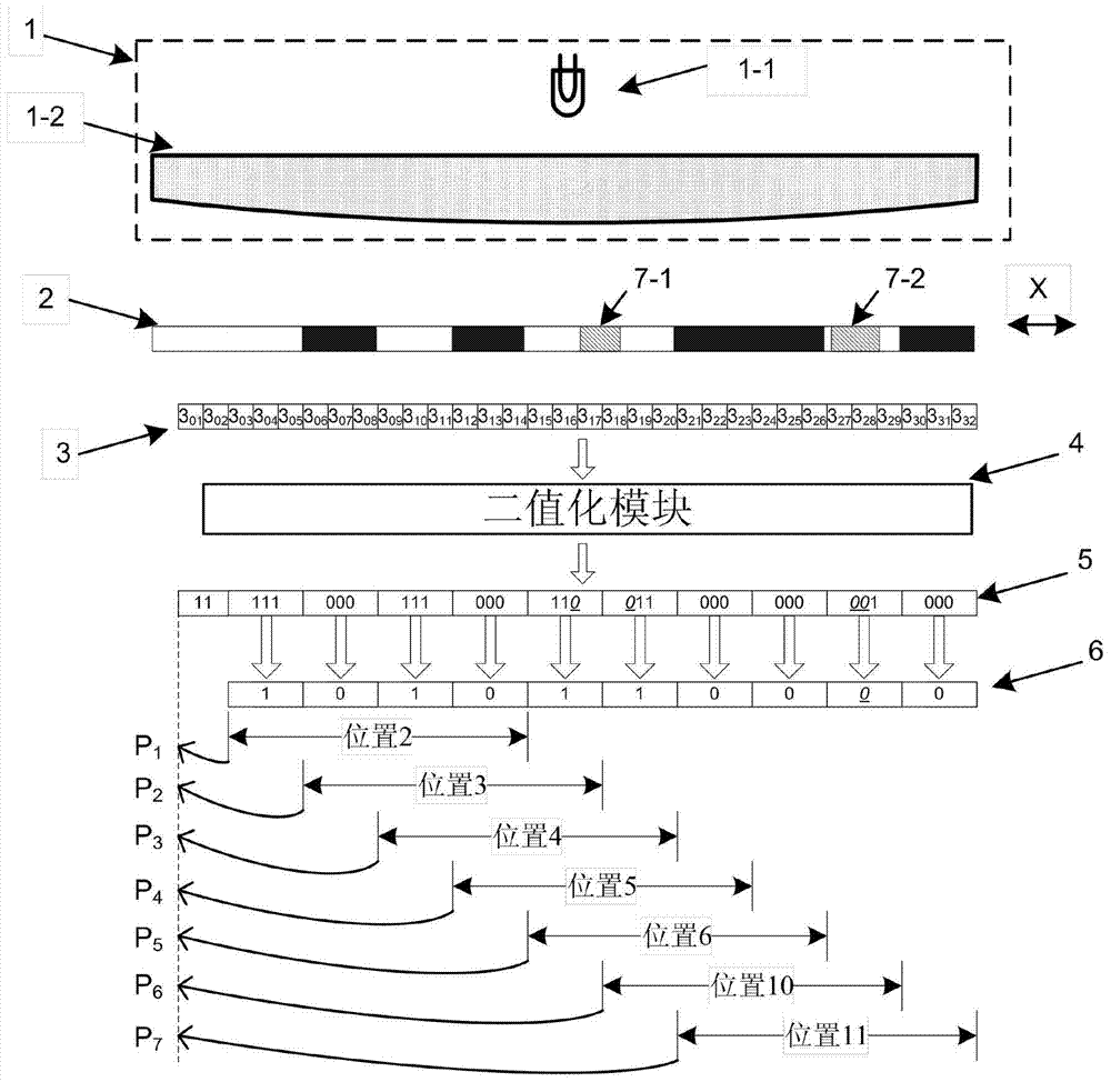
[0020] Specific implementation mode 1. Combination figure 1 To describe the present embodiment, the absolute position measurement method,

[0021] Step 1. Use the photosensitive unit array to scan adjacent multiple absolute position codes, wherein each absolute position code contains unique position information, the position information is continuously arranged in the measurement direction, and each absolute position code is composed of a fixed number of codes Composed of units, each coding unit has optical properties of light transmission or opacity;

[0022] Step 2. The signal obtained by scanning each photosensitive unit of the photosensitive unit array is provided to the binarization module, and the binarization module compares the signal with a certain fixed value to obtain the signal corresponding to each photosensitive unit. The optical properties of the encoding unit;

[0023] Step 3, using multiple photosensitive units in the photosensitive unit array to scan the sa...

specific Embodiment approach 2

[0030] Specific Embodiment 2. This embodiment is an embodiment of the absolute position measurement method described in Specific Embodiment 1: the measuring device involved in this example includes an illumination system 1, an absolute position code 2, a photosensitive unit array 3 and a binarization module 4. Each absolute position code contains unique position information, which is continuously arranged in the measurement direction. Each absolute position code is composed of a fixed number of coding units arranged continuously in the X direction of measurement. The fixed number of codes The unit is determined by the measurement length and the encoding method, and each encoding unit has optical characteristics of light transmission or opacity; the lighting system 1 is composed of a light source 1-1 and a lens 1-2, and the lens 1-2 combines the light source 1 The light emitted by -1 is modulated into parallel light;

[0031] The width W of the coding unit described in this emb...


PUM


Abstract

The invention relates to an absolute position measurement method. The absolute position measurement method solves the problems of low code utilization rate and the like due to the fact that existing methods are only applicable to a Manchester encoding mode and need to scan additional codes and add codes special for error detection. According to the method, optical characteristics reflected by one encoding unit on multiple photosensitive units are voted, and multiple adjacent absolute-position codes are read, so that reliable absolute-position information and current-position pollution status can be provided for subsequent equipment. If the current-position pollution status exceeds a correctable range, a position measurement device stops providing the absolute-position information for the subsequent equipment and gives an alarm. Since one specific photosensitive unit is selected as a measurement point, measurement resolution ratio can be increased.

Description

technical field [0001] The invention relates to an absolute position measurement method. Background technique [0002] Position measuring devices are widely used in processing and measuring industries. Regardless of any application, position measuring devices are required to have extremely high reliability. [0003] The absolute position measuring device can directly obtain the current position information when it is powered on, without the need to find the zero position, so it is more and more widely used. [0004] Absolute position measuring devices include position information in absolute position codes. The absolute position code is composed of coding units arranged in a certain way in the measurement direction. A fixed number of coding units constitutes an absolute position code, which uniquely corresponds to a position information in the measurement direction, and this information is continuously distributed in the measurement direction. [0005] The absolute positio...

Claims


Application Information

Patent Timeline
IPC IPC(8): G01D5/34
Inventor 乔栋孙强吴宏圣曾琪峰蔺春波
Owner CHANGCHUN INST OF OPTICS FINE MECHANICS & PHYSICS CHINESE ACAD OF SCI
Why Eureka
Try Eureka